PCAN-M.2
Part No.: .
MPPK-IPEH-004083 (Single Channel)
MPPK-IPEH-004084 (Dual Channel)
MPPK-IPEH-004085 (Four Channel)
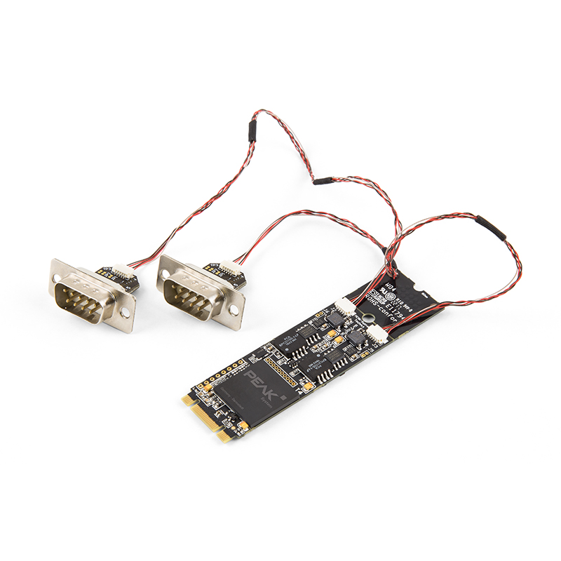
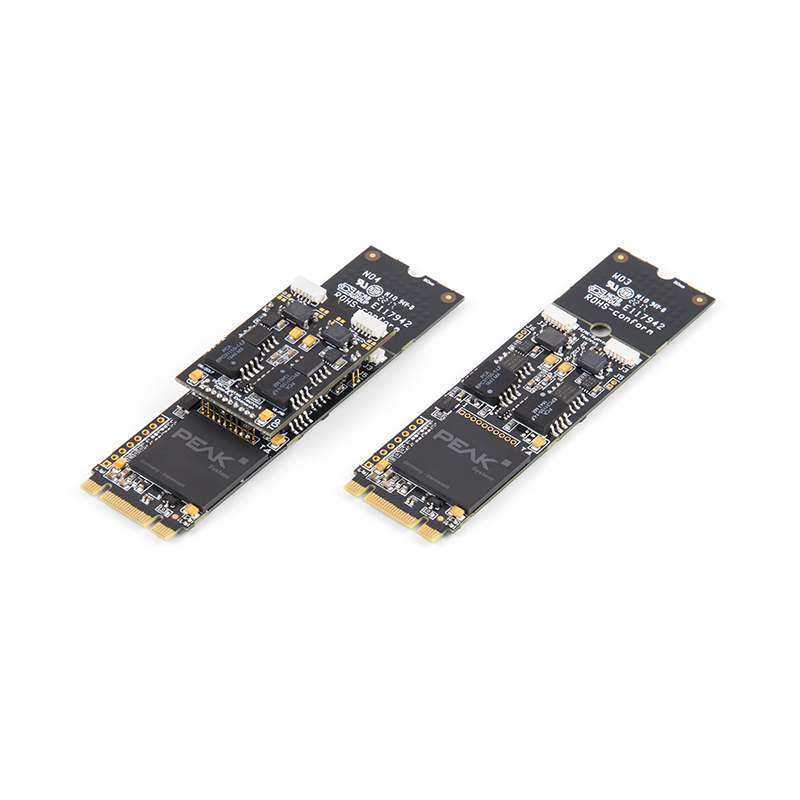
The PCAN-M.2 allows the connection of CAN and CAN FD networks via the M.2 interface (PCIe) of modern computer boards.
*標高電子為德商PEAK SYSTEMS台灣唯一代理商。
產品介紹
Description
The PCAN-M.2 allows the connection of CAN and CAN FD networks via the M.2 interface (PCIe) of modern computer boards. With its small format, the plug-in card is ideal for embedded PCs, single-board computers (SBC), and compact embedded applications. There is a galvanic isolation between the computer and the CAN side up to 300 Volts. The card is available as a single, dual, or four-channel version.
The new CAN FD standard (CAN with Flexible Data rate) is primarily characterized by higher bandwidth for data transfer. The maximum of 64 data bytes per CAN FD frame (instead of 8 so far) can be transmitted with bit rates up to 12 Mbit/s. CAN FD is downward-compatible to the CAN 2.0 A/B standard, thus CAN FD nodes can be used in existing CAN networks. However, in this case the CAN FD extensions are not applicable.
The monitor software PCAN-View and the programming interface PCAN-Basic for the development of applications with CAN connection are included in the scope of supply and support the new standard CAN FD.
Specification
- CAN interface for the M.2 slot (uses PCIe lane)
- 1, 2, or 4 High-speed CAN channels (ISO 11898-2)
- Form factor M.2 type: 2280/2260-B-M; Height: Single and Dual Channel 4.6 mm, Four Channel 10.2 mm; Component height of top side above form factor specification of 1.5 mm
- Complies with CAN specifications 2.0 A/B and FD
- CAN FD support for ISO and Non-ISO standards switchable
- CAN FD bit rates for the data field (64 bytes max.) from 20 kbit/s up to 12 Mbit/s
- CAN bit rates from 20 kbit/s up to 1 Mbit/s
- CAN bus connection via connection cable and D-Sub, 9-pin (in accordance with CiA® 303-1)
- FPGA implementation of the CAN FD controller
- Microchip CAN transceiver MCP2558FD
- Galvanic isolation on the CAN connection up to 300 V, separate for each CAN channel
- CAN termination can be activated through a solder jumper, separately for each CAN channel
- PCIe data transfer via bus master DMA
- DMA memory access operations with 32- and 64-bit addresses
- Measurement of bus load including error frames and overload frames on the physical bus
- Induced error generation for incoming and outgoing CAN messages
- Extended operating temperature range from -40 to 85 °C (-40 to 185 °F)

|
PIN
|
PIN Assigmnet
|
|---|---|
|
1
|
Not connected
|
|
2
|
CAN-L
|
|
3
|
GND
|
|
4
|
Not connected
|
|
5
|
Not connected
|
|
6
|
GND
|
|
7
|
CAN-H
|
|
8
|
Not connected
|
|
9
|
Not connected
|
Product Includes...
- PCAN-M.2 card
- Connection cables incl. D-Sub connector optionally 20 or 40 cm. Other lengths on request
- Device drivers for Windows® 11 (x64), 10 (x64), and Linux
- CAN monitor PCAN-View for Windows®
- Programming interface PCAN-Basic for developing applications with CAN connection
- Programming interfaces for standardized protocols from the automotive sector
- Manual in PDF format
1. Prices and Specifications are subject to change without notice