產品介紹
Description
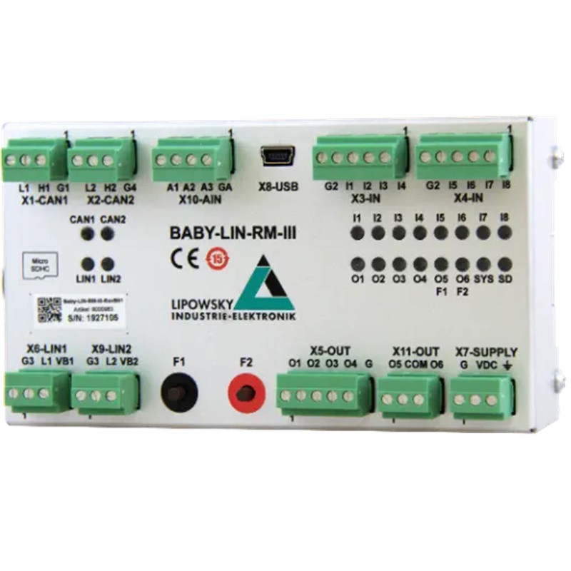
The Baby-LIN-RM-III is a LIN and CAN bus combination device for easy connection to PLC-based EOL systems. With the digital inputs and outputs and the extension to CAN-FD support, all interfaces are provided. In conjunction with our LINWorks software, Marcos can be programmed, with which the Baby-LIN-RM-III serves countless task areas even in stand-alone mode.
The delivery of a Baby-LIN-RM-III system includes the following components:
- Baby-LIN-RM-III device
- USB 2.0 cabel, 1,5m, typ A to typ B-mini
- 6 3-pole plug with screw connection (MCVR 1,5/ 3-ST-3,81)
- 1 4-pole plug with screw connection (MCVR 1,5/ 4-ST-3,81)
- 3 5-pole plugs with screw connection (MCVR 1,5/ 5-ST-3,81)
- Download licence for LINWorks suite (includes LINWorks PC software, USB drivers, sample files and documentation)
Performance Overview
Application areas
- Can be used for PLC coupling, restbus simulation, control unit test, automatic test systems and EOL applications
- Extension and modernisation of test benches to new control units with LIN or CAN bus interface
- Can be used as an autonomous LIN/CAN gateway
- LIN or CAN bus control via digital inputs configurable via LDF/DBC
- Stand-alone mode with freely programmable command sequences possible
- Data logging function possible at 100% bus workload
Technical function
- Supports LIN bus versions 1.2, 1.3, 2.0, 2.1 and 2.2, as well as CAN-FD, CAN-High-Speed and CAN-Low-Speed buses
- Provides 8 input and 6 output 24V signals with 3 analogue inputs
- 2 freely programmable buttons integrated
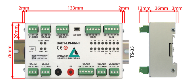
- Compact module for top-hat rail mounting. 76 x 133 x 36mm (H x W x D)
- Galvanically isolated LIN and CAN bus interface
- MicroSD card up to 32 GB
- On-board voltages from 8 - 28V
Compatibility and system requirements
- Windows 7/8/10/11 (32/64 Bit)
- Interface to the DLL library for:
- Windows (x86 & x64), PC based Linux (x86 & x64), ARM based Linux (ARM32 & ARM64)
- Native programming for C/C++ as well as via wrappers in .NET languages, Python, VB6 and LabView are possible
Technical Specificaton
Device
- CPU: ARM Cortex-M7, 300 MHz
- Memory: 32 MB RAM
- 6 red/green multi colored LED: Signal device, microSD card and LIN and CAN-Bus states
- 2 LEDs: Used as digital output indicator, switch button indicator or freely programmable
- 12 LEDs: Used as signal indicator for digital input and outputs
- 2 freely programmable push buttons
- Real-time clock (battery-backed)
- Power supply: 7-32 VDC
- Power supply via 3 pin connector (MC 1,5/ 3-ST-3,81)
- Maximum current consumption: 70 mA @ 24 VDC
- Galvanic isolation of all communication interfaces (LIN- and CANBus, USB, Exception: 4 of the 6 digital outputs)
Interface: LIN
- Up to 2 LIN-Bus interfaces available
- 1 LIN-Bus interface available by default
- 1 LIN-Bus interface optionally available on hardware but not activated, voucher code required
- LIN-Bus connection via 3 pin connector (MCVR 1,5/ 3-ST-3,81)
- LIN-Bus supply voltage: 8-26 VDC
- LIN-Bus baud rate: up to 115200 Baud (Support of protocols outside of the LIN specification)
- Supported LIN versions: V1.2, V1.3,...V2.2
- Supported LIN related protocols: Cooling and SAE J2602
- Maximum signal cable length for LIN-Bus: 30 m
Interface: CAN
- 2 CAN-FD-Bus interfaces according to ISO-11898-1:2015 with data baudrates up to 8 MBit/s available on hardware but not activated, voucher code required
- Both CAN-FD-Bus interfaces usable as high speed interfaces (CAN-HS) according to ISO-11898
- Used CAN-Bus driver for CAN-FD and CAN-HS: MCP2562FD
- One CAN-FD-Bus interface usable as fault tolerant low speed interface (CAN-LS) according to ISO-11519, voucher code required
- Used CAN-Bus driver for CAN-LS: TJA1055
- CAN-FD-Bus connection via 3 pin connector (MCVR 1,5/ 3-ST3,81)
- Maximum baudrate: CAN-FD: 8 MBit/s, CAN-HS: 1 MBit/s, CANLS: 125 kBit/s
- Maximum signal cable length for CAN-Bus: 30m
Interface: Digital I/O
- 8 digital inputs
- 4 digital low-side outputs
- 2 electrically isolated digital output
- Digital I/O available via 3 5 pin connectors (MCVR 1,5/ 5-ST-3,81) and 1 3 pin connector (MCVR 1,5/ 3-ST-3,81)
- 2 digital inputs can be used to read PWM signals
- 4 digital outputs can be used to output PWM signals
Interface: Analog I/O
- 3 electrically isolated analog inputs
- Measuring range up to 25 V, Voltage tolerance up to 33 V
- Analog I/O available via 4 pin connector (MC 1,5/ 4-ST-3,81)
Interface: microSD card
- Supported card types: microSD cards, microSDHC cards
- Supported file system: FAT-32, FAT-16
- Maximum card size: 32 GB
- It is planned to use the microSD card slot for logging purposes in the future. Right now it is without function.
Case:
- Degree of protection: IP20
- Operating temperature: -20°- +60°Celsius
- Weight: 250 g
- Case dimensions [mm]: 136 x 76 x 36 (L x W x H) Elements like connectors, buttons, and the top hat rail mounting adapter are not included.
- Mounting: Top hat rail (TS 35):
Ordering Information
- Baby-LIN-RM-III (8000983) - Multibus simulation device with I/O interface.