CS1110 Vce Sat probe
Part No.: MPCS-CS1110-Vce-Sat-probe
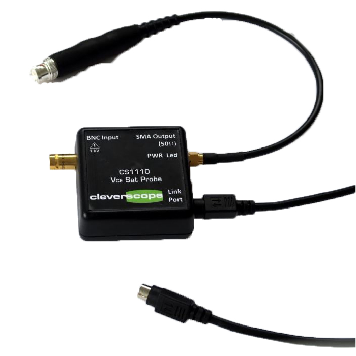
Includes isolated power and control Link cable to CS448.
產品介紹
CS1110 Vce Sat probe
Works with the CS400 Series scopes. Vce Sat probe, clips at 5V to allow isolated measurement of transistor VCEsat while VCE swings up to 1000V. Includes isolated power and control Link cable to CS448.
Summary
The CS1110 VCE Sat probe is used to measure the saturation voltage of a switching transistor. It uses a 6mA high compliance current source with steering logic to measure the transistor forward voltage while the voltage across the device is less than about 5.2V. Above 5.3V the VCE Sat probe is disconnected from the Unit Under Test (UUT) and the current flows through an alternate load. It is expected that the UUT will have a good deal more than 6mA flowing through it. The CS1110 is designed to work into a 50 ohm load.
The CS1110 is rated for operation over the source voltage range of +1kV to -9V. Below approx -12.4V an internal fuse will blow, and the CS1110 will need to be repaired. Do not connect the CS1110 to negative swinging sources.
The CS1110 is powered by +5V sourced by the CS448 link port (pin 1) via an 8 pin Mini Din Connector. It also includes two controls. IN1 (pin 8) when high turns on a 0V reference. In2 (pin 5) when high turns on a 2.495V reference. These are used by the CS448 to calibrate the CS1110 for gain and offset. The CS1110 is supplied ready to give good performance without calibration. The power and control signals are isolated via a low capacitance isolated power supply and TI ISO784DWW logic isolators. The operating withstand voltage is >1kV. In addition the active portion of the CS1110 is shielded and isolated to ensure it can be used to measure the high side transistor while it is operating.
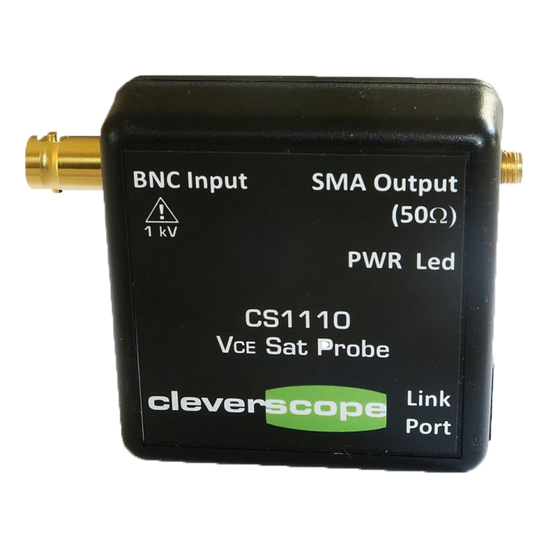
The BNC input is connected via coax to the UUT. Do not use a scope probe as it has >300 ohm series resistance which will deliver incorrect results.
The SMA output is limited to an output voltage range of 0 - 5.3V. It has 50 ohm source impedance and is designed to drive a 50 ohm load via coax. The destination load will see a maximum 140 mW dissipation.
The PWR Led is on the isolated side, and is on when power is applied.
The Link Port is used to power and control the CS1110. Operating current without a 50 Ohm load is 175mA and with a 50 Ohm load 275 mA.
Connections
The probe is supplied with an SMA to terminated BNC socket to plug into the oscilloscope. The supplied
link port cable plugs into the CS448 Link port. The customer supplies the BNC cable to the UUT.
The BNC and cable should be rated for the operating voltage.
IMPORTANT: There are un-insulated metal parts accessible for contact. Lethal voltages could be present. So not touch any part of the CS1110 or cables while exposed to high voltages.
Specification
Measured Specifications are:
| Parameter | Value (typical) | |
|---|---|---|
| Power Supply Voltage | 5V | |
| Power Supply Current - non Terminated | 175 mA | |
| Power Supply Current - 50 Ω Terminated | 275 mA | |
| Current Source for Voltage Sensing | 6 mA | |
| Max Vin | 1000V | |
| Min Vin | -9V | |
| Max Measured VCE SAT | 5.2V | |
| Min Measured VCE SAT | 0V | |
| Fall Time | <10ns | |
| Rise Time | <10ns | |
| Recovery after switch (mismatch oscillation) | <80ns | |
| Size (not including connectors) | 65 x 65 x 28 mm | |
Measurements
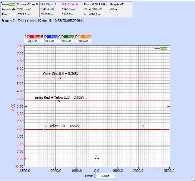
A CS448 was used for measurements, with the Control Panel Probe set to Vsat . For a static test,the CS1110 can be used to measure the forward voltage of an LED or diode:
CS1090 base test of the CS1110
For a dynamic test we used the CS1090 Half bridge.
The CS1110 probe was used to measure the CS1090 500V half bridge which swings an output 500V in about 7ns. The transistors are not loaded, and so do not exhibit forward voltage. This makes them a good test subject.
Here is the 50 kHz CS1090 output - Chan A is SW2, switching between 0 and 500V in about 7ns. Chan B is the CS1110 VCE Sat probe output. As the switch transistors are not loaded the indicated saturation voltage is very low:
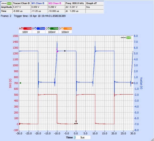
The VceSat probe voltage falls very rapidly when the Lower Switch transistor turns on (recall Chan A is SW2 which is the opposite half bridge). In the Marker period 1-2, the Switch is off, and we are in the dead time period. The upper switch transistor in SW1 then turns on, while the lower transistor in Switch 2 is on.
We can see the current steering system saturating at about 5.4 V (see the Tracer value) while the upper switch transistor is on.
Measurements were carried out at 7, 70 and 500V switching as shown on the next page, where we zoom in time on the waveforms above.
Zoom to 1200 ns wide
Chan A is the opposing switch - SW2. Chan B is the CS11 10 VCE Sat Probe output.
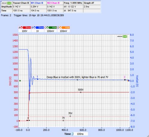
Zooming in to the transition, the fall time is approximately the same as the SW2 rise time.
However we see oscillation that last for approx 60 ns after the fall.
We believe the oscillation is a matching problem. The impedance of the switch transistor is very low (<1 ohm) and it is driving a 50 ohm coax terminated in a high impedance current source. These might simply be reflections due to mismatch. We will be carrying out further test to determine if a mitigation is possible.
All the same, meaningful results can be gain after 60- 80ns.
