Onboard Diagnosis II Simulator
Part No.: MPLCNL-Onboard-Diagnosis-II-Simulator
This course demonstrates how to read out emission data with the help of the onboard diagnosis unit, interpret the data and use the results as a basis for eliminating systemic faults.
產品介紹
Onboard Diagnosis II Simulator
This course demonstrates how to read out emission data with the help of the onboard diagnosis unit (OBD II or EOBD), interpret the data and use the results as a basis for eliminating systemic faults. Students have the possibility to adjust various parameters on their own to see how these settings affect the tester. They also have the opportunity to tap the CAN transmission signal to display it on the oscilloscope.
List of Articles
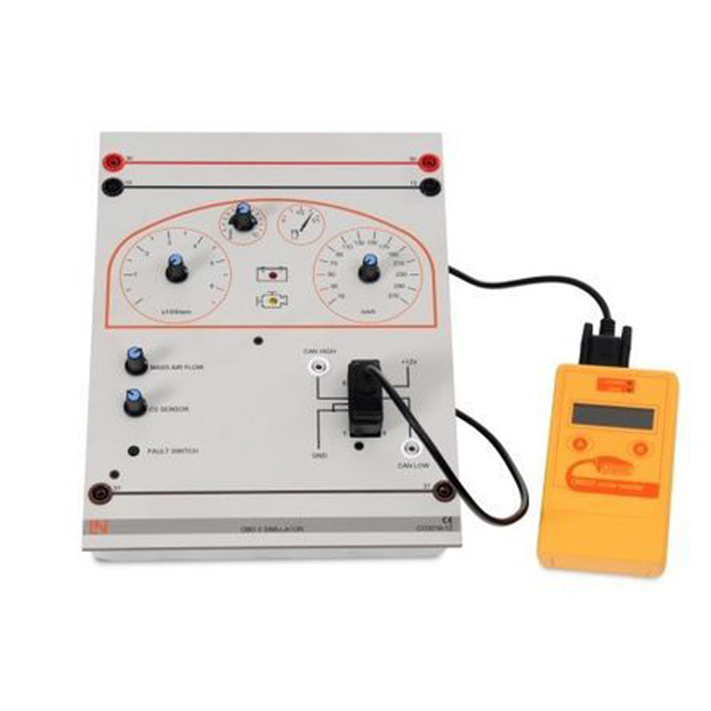
OBD II Simulator with CAN Interface and Scan Tool
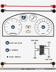
This OBD II simulator can be used for simulating exhaust gas data. Potentiometers allow for sensor data, such as speed or rev-count sensors, to be altered “during travel”, so to speak. In addition, buttons are provided to simulate faults in the vehicle, which leaves a fault entry in the electronic control unit and causes the malfunction indicator light to display. The relevant button can then be used again to cancel these functions in the tester. In this way it is possible to practically analyse test conditions in a much easier fashion than on a full-scale vehicle, as the latter would mean physically manipulating the electrical system of the vehicle itself.
Technical data
- Original OBDII/EOBD interface
- CAN interface
- Fault simulation switches
- Current vehicle data can be modified and read, including air flow, engine temperature, speed and rev count
- Inputs/outputs: 4mm sockets
- 2 Safety connection plugs, red, 19/4mm
- 1 Safety connection plugs, black, 19/4mm
- Dimensions: 297 x 228 x 70mm
- Weight: 1.2kg
OBD Scantool accessories:
All protocols:
- PWM
- VPWM
- ISO9141-2
- KWP2000 5baud init
- KWP2000 fast init
- CAN
- Integrated software and fault database featuring well over 500 fault codes with explanatory text.
- Multilanguage
- Function for clearing MIL fault display on the dashboard display
- Fault codes can be read and deleted
- Selected freeze-frame environments can be invoked.
- Simple operation via intelligent menus using just two buttons.
Additionally Required
Ignition / Starter Switch

Safety ignition/starter switch with three switching levels and settings for energizing terminals 75, 15 and 50. Connections for the fuses are established via 4mm safety jacks, which can be bridged in an organized manner by means of compact jumpers for feeding from terminal 15 or 30. To facilitate an overview for students, the power supply installation is highlighted by means of a colour scheme according to DIN72551 at the board's upper and lower edges.
- Inputs and outputs: 4mm safety jacks
- Dimensions: 297 x 228 x 90 mm
- Weight: 0.8 kg
Additionally Recommended
Panel Mounting Frame for Table, T-Shaped Base, 1 Level

Panel mounting frame with aluminium profile rails for mounting experiment panels of height matching DIN A4 (297 mm). Die Aluminium profile rails with inward-facing brushes allow for rapid and quiet mounting of experiment panels without tools.
- Side pieces with T-shaped base under the bottom rail
- Side pieces made of rectangular steel tubing (30x20x2mm), powder coated grey surface (RAL 7047)
- 2 natural brushed aluminium profile rails with inward-facing brush rails
- Can be set up on laboratory benches with or without power supply ducts or on any other existing surface
- Dimensions WxH: 724 x 400 mm, 1 level
Multi13S Digital Multimeter
.jpg)
Universal precision lab multimeter and temperature meter with IR interface for high-quality, universal measurement and testing in educational settings, power plants, process control installations etc.
- 3¾-digit multimeter; resolution: ±3,100 digits
- Measurement classification CATII-1000 V
- Can be connected to UniTrain system via IR interface
- Voltage and current measuring ranges: 30 mV-1000 V DC, 3 V-1000 V AC; 3 mA-16 A DC; 30 mA-10 A AC
- Resistance ranges: 30 ohm-30 Mohm
- Special functions: °C for temperature measurements using PT100/1000 thermocouple (optional accessory)
- Continuity and diode testing
- Automatic range selection and battery shut-off, min./max. and data hold function
- Safety fuse for current measurement range up to 300 mA
- Protection against high currents in the mA range for nominal voltage of 1000 V
- Display with bar chart and backlighting
- Includes protective sleeve, measuring leads, 1 x spare fuse, 9V battery, calibration certificate
Media
Manual for "Onboard Diagnostics: EOBD/OBDII"

High-quality, bound, colour teachers' manual with rigid spine, including solutions. CD-ROM with additional students' manual, including exercises and worksheets.
Details:
- Theoretical background
- Colour CAD drawings for experiment set-ups and circuits
- Exercises and worksheets
- Printed on high-quality 100-g/m² colour copy paper, book cover on 210-g/m² glossy paper
Training contents:
- What is OBD?
- Requirements concerning OBD II and EOBD
- Differences from OBD I
- Differences between OBD II and EOBD
- Fault display
- Driving cycle
- Diagnostics interface
- Protocols
- Fault codes
- Readiness code
- Summary of EOBD
- OBD knowledge test
- Diagnostic unit
- Functions of a diagnostic unit
- Diamex operation
- Diamex operation – part 2
- Launch CRecoder
- Simulator tests
- Reading out actual values
- Reading out fault codes
- Freeze frames (fault environment)
- Clearing the fault memory
- Data signals
- CAN bus terminating resistors
- Fault diagnosis
- Exercise
- Fault 1
- Fault 2
- Fault 3
- Fault 4
- Workshop job
- Job worksheet
- Fault diagnosis with an optional ADT
- Air-flow meter malfunction
- Injection valve malfunction
- Tests on an automobile
- Opel Corsa D
- Reading out actual values
Power Supply
Power Supply, 13.5 V, 45 A
.jpg)
The "Power supply" module is part of ´various training systems including the "Modular engine management" system. It provides power to various components in a similar to the way they are supplied in practice in a real engine by means of a 12 V battery. The module employs a 600 watt power unit which can supply a maximum current of 45 A at 13.5 V between its screw terminals. To protect the training system, a maximum current of 30 A can be tapped via the 4-mm safety sockets. This protective function is implemented by electronic monitoring of the 4mm safety sockets. Thanks to the high-resolution printing on the front panel, the module can immediately be identified as a typical car battery.
Technical highlights:
- Stable on-board network voltage of 13.5 volts
- Automatic cut-out without fuses
- Short-circuit protection
- Typical appearance of a vehicle battery thanks to high-resolution printed image of a starter battery
- Maximum current: 45 A
Technical details:
- Operating voltage: 90-264 V AC (47-63 Hz)
- Dimensions: 297 x 227 x 180 mm (HxWxD)
- Weight: 1.6 kg