Modular Engine Management "Gasoline Direct Injection"
Part No.: MPLCNL-Modular-Engine-Management-Gasoline-Direct-Injection
The safety measurement sockets and the "all-in-one" measuring apparatus offer students multiple options for carrying out measurements on the training system.
產品介紹
Modular Engine Management "Gasoline Direct Injection"
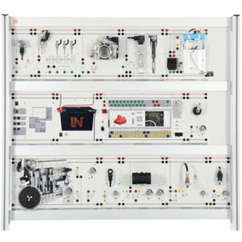
This engine management system provides trainees with all the necessary components (engine control unit, sensors, actuators, power supply) for modular assembly and configuration. This means that the complexity of the system can be adapted to need and an in-depth understanding can be gained of communication between individual sensors or actuators and the engine control unit, considering input, processing and output as a basic principle.
To ensure the perfect symbiosis between theory and practice, all the modules have genuine, fully functioning components wherever possible. These are then complemented with realistic drawings. To further enhance the practical aspect and make it true to life, each module has a simulation mode and an authentic mode, such that it is possible to measure the actual air-flow by mass using the authentic flow meter. In addition, the response of the entire system can be analysed when plugs and connecting leads are removed. The on-board diagnostic (OBD) connector on the control unit allows previously activated simulated faults to be read out.
The safety measurement sockets and the "all-in-one" measuring apparatus offer students multiple options for carrying out measurements on the training system. The accompanying course software provides not only the extensive interactive and theoretical content but also the necessary virtual instruments to convert your own Windows device into a powerful, multi-functional measurement platform (voltmeters, oscilloscope) with the simultaneous capability to document the results of measurements
To meet the requirements for such training systems, the individual modules are provided with short-circuit protection so that they have the suitable resilience to faulty operation.
Basic Equipment Set, Consisting of...
Programmable Engine Control Unit
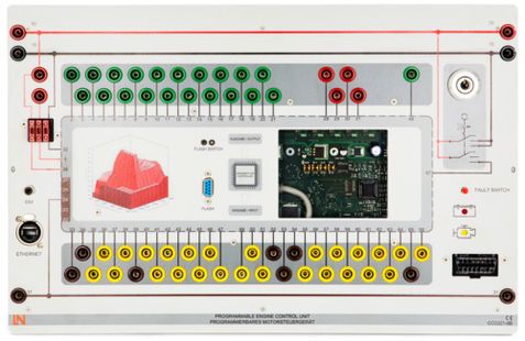
The core of the "Modular engine management system" is the engine control unit which can be programmed as needed. It has its own modifications for educational purposes which are perfect for showing how the controller receives input, processes it and outputs the appropriate signals. All the control unit's pins are connected to sockets on the neatly laid out front panel so that measurements can be made on them directly. Thanks to the colour-coding of the 4-mm safety sockets, it is easy to identify the actual function of each of the pins (sensors, actuators, power, ground) at a glance. The control unit also proves to be multi-talented in the area of diagnostics. It is possible to use the fault switches or the OBD socket to read out standard P0 codes but also to monitor real-time data and modifications with the help of the Ethernet port and matching software. This enables you to cover the telecommunications topics of how Ethernet and IP are used in vehicles
Technical highlights:
- Changing sets of parameters via Ethernet link
- Software status can be written to flash memory via RS 232 port
- Measurement and configuration software can also be connected via Ethernet
- On-board diagnostics via OBD port, malfunction indicator light (MIL) and fault simulation switches
- Indicator light for detection of rpm signal
- Indicator light for detection of switch enabling flash memory writes
- Status display for ignition voltage
- Ignition/start switch
- 26 inputs for various sensors with 4-mm safety measurement sockets
- 21 power outputs for various actuators with 4-mm safety measurement sockets
- Digital sensor ground terminals connected to 4-mm safety measurement sockets
- Analog sensor ground terminals connected to 4-mm safety measurement sockets
- Central power and ground rails in DIN colours
- Fuses: 3 x 15 A
- 1 cinch output for additional simulation signals
- Inputs and outputs: 4-mm safety sockets
Technical details:
- Operating voltage: 12 V
- Dimensions: 297 x 445 x 180 mm (HxWxD)
- Weight: 3.4 kg
Output Stage with High-Pressure Injection Valves
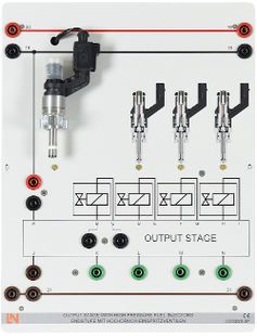
The "Output stage with high-pressure injection valves" module is part of the “Modular engine management” training system. Its symbiosis between authentic components and digitally rendered graphics means you can get the full educational potential out of the module. Trainees not only learn the authentic look and feel of the components but can also associate this actual appearance with the corresponding circuit symbol, which is a major help in reading and understanding circuit diagrams. Depending on the actual module, there may also be a 3D drawing as well as the circuit symbol, which shows details of the component. Since the 4-mm safety sockets used for the module use the same colour-coding as the control unit, not only is the basic function of each terminal self-explanatory but also the dangers of incorrect wiring are minimised. Even if wiring is done incorrectly, all the sensors and actuator modules possess inherent safety circuitry to protect them against short-circuits.
Technical highlights:
- Real MED – injection valve installed laterally into the cylinder
- Cross-sectional depiction of the injection valve
- Depiction of the fuel injection sequence of a 4-cylinder engine
- Actuation of each injection valve
- Circuit symbol with measuring points
- Output stage to deliver boost voltage
- Short-circuit proof
Technical details:
- Operating voltage: 12 V
- Dimensions: 297 x 227 x 180 mm (HxWxD)
- Weight: 1.3 kg
E-Gas Throttle Valve
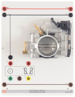
The "E-Gas throttle valve" module is part of the “Modular engine management” training system. Its symbiosis between authentic components and digitally rendered graphics means you can get the full educational potential out of the module. Trainees not only learn the authentic look and feel of the components but can also associate this actual appearance with the corresponding circuit symbol, which is a major help in reading and understanding circuit diagrams. Depending on the actual module, there may also be a 3D drawing as well as the circuit symbol, which shows details of the component. Since the 4-mm safety sockets used for the module use the same colour-coding as the control unit, not only is the basic function of each terminal self-explanatory but also the dangers of incorrect wiring are minimised. Even if wiring is done incorrectly, all the sensors and actuator modules possess inherent safety circuitry to protect them against short-circuits.
Technical highlights:
- Real throttle valve with position sensor and actuator
- Circuit symbol with measurement points
- Short-circuit proof
- Switches for real and simulation mode of the throttle valve opening angle
- Continuous simulation of the throttle valve opening angle
Technical details:
- Operating voltage: 5 V, 12 V
- Dimensions: 297 x 227 x 180 mm (HxWxD)
- Weight: 1.3 kg
Single Spark Ignition Coil
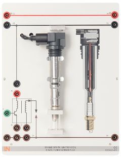
The modular unit "Single spark ignition coil" is a component of the "Modular Engine Management" training system. Thanks to the symbiosis of real components with digitally generated graphics it is possible to fully exploit the maximum possible knowledge transfer of the individual module. The trainee gets to know, on the one hand, how the component really looks and how the part feels to the touch but can also link the physical appearance directly to the corresponding circuit symbol which is critical in helping individuals read and understand circuit diagrams. Depending on the module there are besides circuit symbols also 3D illustrations which depict the respective component in detail. Since the 4-mm safety sockets of the module have the same colour coding as the control unit, the basic function of the respective connections is not only self-explanatory but also minimises the danger of making faulty wiring connections. In the event a mistake is made in the wiring, the sensor and actuator modules are equipped with built-in safety circuitry which protects against short-circuits.
Technical highlights:
- Real compact ignition coil including spark plugs
- Generates a real ignition spark
- Circuit symbol with measurement points
- Short-circuit proof
Technical details:
- Operating voltage: 12V
- Dimensions: 297 x 227 x 180mm (HxWxD)
- Weight: 1.3kg
Fuel Pump
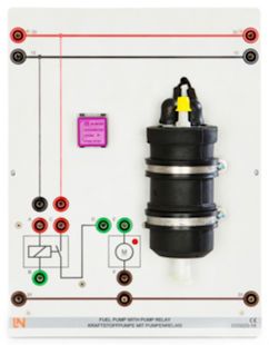
The "Fuel pump" module is part of the “Modular engine management” training system. Its symbiosis between authentic components and digitally rendered graphics means you can get the full educational potential out of the module. Trainees not only learn the authentic look and feel of the components but can also associate this actual appearance with the corresponding circuit symbol, which is a major help in reading and understanding circuit diagrams. Depending on the actual module, there may also be a 3D drawing as well as the circuit symbol, which shows details of the component. Since the 4-mm safety sockets used for the module use the same colour-coding as the control unit, not only is the basic function of each terminal self-explanatory but also the dangers of incorrect wiring are minimised. Even if wiring is done incorrectly, all the sensors and actuator modules possess inherent safety circuitry to protect them against short-circuits.
Technical highlights:
- Authentic fuel pump
- Short-circuit-proof
- Circuit symbol with measuring points
Technical details:
- Operating voltage: 12 V
- Dimensions: 297 x 116 x 180 mm (HxWxD)
- Weight: 0.8 kg
Drive Unit with Crankshaft, Camshaft and Engine Temperature Sensor
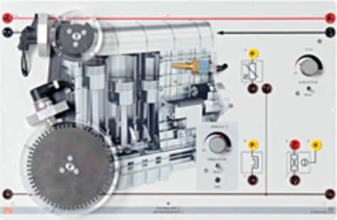
The "Drive unit 2" module is part of the “Modular engine management” training system. Its symbiosis between authentic components and digitally rendered graphics means you can get the full educational potential out of the module. Trainees not only learn the authentic look and feel of the components but can also associate this actual appearance with the corresponding circuit symbol, which is a major help in reading and understanding circuit diagrams. Depending on the actual module, there may also be a 3D drawing as well as the circuit symbol, which shows details of the component. Since the 4-mm safety sockets used for the module use the same colour-coding as the control unit, not only is the basic function of each terminal self-explanatory but also the dangers of incorrect wiring are minimised. Even if wiring is done incorrectly, all the sensors and actuator modules possess inherent safety circuitry to protect them against short-circuits.
Technical highlights:
- Authentic crankshaft sensor
- Authentic camshaft sensor
- Authentic engine temperature sensor
- Short-circuit-proof
- Circuit symbol with measuring points
- Switch for selecting between actual and simulated engine temperature modes
- Continuous simulation of temperature changes in a range from -20 to 110°C.
- Switch for selecting between actual and simulated crankshaft and camshaft modes
- Continuous simulation of speed or actual control by accelerator pedal sensor.
- High-resolution printed cut-away of R4 engine
Technical details:
- Operating voltage: 5 V
- Dimensions: 297 x 445 x 180 mm (HxWxD)
- Weight: 3.4 kg
Broadband lambda sensor
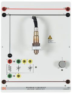
The "Broadband lambda sensor" module is part of the “Modular engine management” training system. Its symbiosis between authentic components and digitally rendered graphics means you can get the full educational potential out of the module. Trainees not only learn the authentic look and feel of the components but can also associate this actual appearance with the corresponding circuit symbol, which is a major help in reading and understanding circuit diagrams. Depending on the actual module, there may also be a 3D drawing as well as the circuit symbol, which shows details of the component. Since the 4-mm safety sockets used for the module use the same colour-coding as the control unit, not only is the basic function of each terminal self-explanatory but also the dangers of incorrect wiring are minimised. Even if wiring is done incorrectly, all the sensors and actuator modules possess inherent safety circuitry to protect them against short-circuits.
Technical highlights:
- Real broadband sensor
- Circuit symbol with measuring points
- Continuous simulation of the lambda value
- Short-circuit proof
Technical details:
- Operating voltage: 12 V, 5 V
- Dimensions: 297 x 116 x 180 mm (HxWxD)
- Weight: 0.8 kg
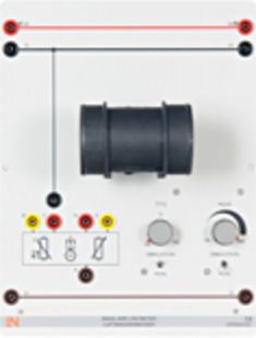
Mass Air Flow Sensor
The "Mass air flow sensor" module is part of the “Modular engine management” training system. Its symbiosis between authentic components and digitally rendered graphics means you can get the full educational potential out of the module. Trainees not only learn the authentic look and feel of the components but can also associate this actual appearance with the corresponding circuit symbol, which is a major help in reading and understanding circuit diagrams. Depending on the actual module, there may also be a 3D drawing as well as the circuit symbol, which shows details of the component. Since the 4-mm safety sockets used for the module use the same colour-coding as the control unit, not only is the basic function of each terminal self-explanatory but also the dangers of incorrect wiring are minimised. Even if wiring is done incorrectly, all the sensors and actuator modules possess inherent safety circuitry to protect them against short-circuits.
Technical highlights:
- Authentic hot-film mass air flow sensor
- Circuit symbol with measuring points
- Short-circuit-proof
- Built-in function for measuring intake air temperature
- Switch for selecting between actual and simulated intake air temperature modes
- Continuous simulation of temperature changes in a range from -20 to 110°C.
- Switch for selecting between actual and simulated air flow modes
- Continuous simulation of mass air flow
Technical details:
- Operating voltage: 12 V, 5 V
- Dimensions: 297 x 227 x 180 mm (HxWxD)
- Weight: 1.3 kg
Rail Pressure Sensor (MED)
.jpg)
The module "Rail pressure sensor" for MED engines is part of the “Modular engine management” training system. Its symbiosis between authentic components and digitally rendered graphics means you can get the full educational potential out of the module. Trainees not only learn the authentic look and feel of the components but can also associate this actual appearance with the corresponding circuit symbol, which is a major help in reading and understanding circuit diagrams. Depending on the actual module, there may also be a 3D drawing as well as the circuit symbol, which shows details of the component. Since the 4-mm safety sockets used for the module use the same colour-coding as the control unit, not only is the basic function of each terminal self-explanatory but also the dangers of incorrect wiring are minimised. Even if wiring is done incorrectly, all the sensors and actuator modules possess inherent safety circuitry to protect them against short-circuits.
Technical highlights:
- Real rail pressure sensor
- Short-circuit proof
- Circuit symbol with measuring points
- Switch for real and simulated rail pressure operating mode
- Continuous simulation of rail pressure in a range from 0 up to 200 bar
Technical details:
- Operating voltage: 5 V
- Dimensions: 297 x 116 x 180 mm (HxWxD)
- Weight: 0.8 kg
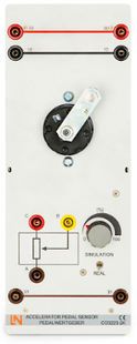
Throttle Pedal Position Sensor
The "Throttle position sensor" module is part of the “Modular engine management” training system. Its symbiosis between authentic components and digitally rendered graphics means you can get the full educational potential out of the module. Trainees not only learn the authentic look and feel of the components but can also associate this actual appearance with the corresponding circuit symbol, which is a major help in reading and understanding circuit diagrams. Depending on the actual module, there may also be a 3D drawing as well as the circuit symbol, which shows details of the component. Since the 4-mm safety sockets used for the module use the same colour-coding as the control unit, not only is the basic function of each terminal self-explanatory but also the dangers of incorrect wiring are minimised. Even if wiring is done incorrectly, all the sensors and actuator modules possess inherent safety circuitry to protect them against short-circuits.
Technical highlights:
- Authentic throttle (accelerator pedal) position sensor with kick-down function
- Short-circuit-proof
- Circuit symbol with measuring points
- Switch for selecting between actual and simulated modes
- Continuous simulation of pedal position
Technical details:
- Operating voltage: 12 V
- Dimensions: 297 x 116 x 180 mm (HxWxD)
- Weight: 0.8 kg
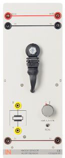
Knock Sensor
The modular unit "Knock sensor" is a component of the "Modular Engine Management" training system. Thanks to the symbiosis of real components with digitally generated graphics it is possible to fully exploit the maximum possible knowledge transfer of the individual module. The trainee gets to know, on the one hand, how the component really looks and how the part feels to the touch but can also link the physical appearance directly to the corresponding circuit symbol which is critical in helping individuals read and understand circuit diagrams. Depending on the module there are besides circuit symbols also 3D illustrations which depict the respective component in detail. Since the 4-mm safety sockets of the module have the same colour coding as the control unit, the basic function of the respective connections is not only self-explanatory but also minimises the danger of making faulty wiring connections. In the event a mistake is made in the wiring, the sensor and actuator modules are equipped with built-in safety circuitry which protects against short-circuits.
Technical highlights:
- Real knock sensor
- Circuit symbol with measurement points
- Switch for real and simulation operating modes
- Simulation of normal combustion and combustion subject to knocking
- Short-circuit proof
Technical details:
- Operating voltage: 5V
- Dimensions: 297 x 116 x 180 mm (HxWxD)
- Weight: 0.8 kg
Rail Pressure Control Valve (PCV)
.jpg)
The "Rail pressure control valve (PCV)" module is part of the “Modular engine management” training system. Its symbiosis between authentic components and digitally rendered graphics means you can get the full educational potential out of the module. Trainees not only learn the authentic look and feel of the components but can also associate this actual appearance with the corresponding circuit symbol, which is a major help in reading and understanding circuit diagrams. Depending on the actual module, there may also be a 3D drawing as well as the circuit symbol, which shows details of the component. Since the 4-mm safety sockets used for the module use the same colour-coding as the control unit, not only is the basic function of each terminal self-explanatory but also the dangers of incorrect wiring are minimised. Even if wiring is done incorrectly, all the sensors and actuator modules possess inherent safety circuitry to protect them against short-circuits.
Technical highlights:
- Authentic rail PCV
- Short-circuit-proof
- Circuit symbol with measuring points
Technical details:
- Operating voltage: 12 V
- Dimensions: 297 x 116 x 180 mm (HxWxD)
- Weight: 0.8 kg
Power Supply
Power Supply, 13.5 V, 45 A
.jpg)
The "Power supply" module is part of ´various training systems including the "Modular engine management" system. It provides power to various components in a similar to the way they are supplied in practice in a real engine by means of a 12 V battery. The module employs a 600 watt power unit which can supply a maximum current of 45 A at 13.5 V between its screw terminals. To protect the training system, a maximum current of 30 A can be tapped via the 4-mm safety sockets. This protective function is implemented by electronic monitoring of the 4mm safety sockets. Thanks to the high-resolution printing on the front panel, the module can immediately be identified as a typical car battery.
Technical highlights:
- Stable on-board network voltage of 13.5 volts
- Automatic cut-out without fuses
- Short-circuit protection
- Typical appearance of a vehicle battery thanks to high-resolution printed image of a starter battery
- Maximum current: 45 A
Technical details:
- Operating voltage: 90-264 V AC (47-63 Hz)
- Dimensions: 297 x 227 x 180 mm (HxWxD)
- Weight: 1.6 kg
Measuring Instruments
Modular Measurement Interface
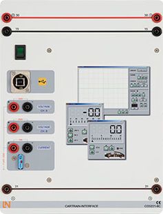
The CarTrain Interface takes the form of a DIN A4 experiment card with rounded corners, colour-coded in compliance with DIN72551 for educational assistance.
Safety measurement sockets are also coded on the basis of DIN72551.
The design resembles circuit diagrams depicted in a detached or exploded view with power supply wiring running between panels.
- Interface for multimedia experiment literature – measurements need to be copied into the experiment instruction pages using drag and drop.
- Two voltage values and one current can all be measured simultaneously
- 3-channel oscilloscope function can be used at the same time as the multimeter display
- Measurement range: V<250 V=/~, I<15A=/~ direct measurement within the circuit
- USB interface
- External power supply to ensure measurements can be made even when short circuits are present
- Current measuring range protected by automatic circuit breaker
- Dimensions: 228 x 296 x 125 mm (WxHxD)
- Weight: 2 kg
Media
Interactive Lab Assistant: Gasoline Direct Injection (Modular)
.jpg)
The course "Gasoline Direct Injection" in conjunction with the "Modular Engine Management: Gasoline Direct Injection" system constitutes the perfect symbiosis between theory and practice. Thanks to its rigorous and logical design it promotes the natural inquisitiveness of the trainee and puts that person in a position to easily comprehend a complex engine management system. This is supported by a host of animations for which a complete common rail engine has been digitalised. This gives trainees the opportunity to experience how sensors and actuators work and operate from a totally new perspective.
It is explained interactively how the hardware is operated and how the numerous experiments are carried out. This significantly reduces the time needed to prepare the individual experiments. Particularly due to the fact that all of the measuring instruments (e.g. oscilloscopes and voltmeters) are already integrated into the course. Significantly boosting the trainee's efficiency means there is more time for more important matters. Due to a strict selection of theoretical material, all of the important topics are covered that contribute to understanding and which are fundamental to developing skills and competence in diagnostics.
To round off the overall package, the course also contains chapter-specific quizzes which test the knowledge level of each and every trainee. Accordingly, both the trainee and the instructor are always provided feedback on the current level of learning performance.
Additionally Recommended
Protection Cover for Three-Level Experiment Trolleys

- For protecting equipment from dust and damp
- For keeping equipment out of sight (the cover must not be transparent, so is therefore opaque)
- Colour: matt dark grey with printed LN logo in orange)
- Material: nylon fabric with polyurethane coating
- High resistant to tearing, impregnated to be washable and waterproof
Accessories
Mobile Aluminum Experiment Stand, 3 Levels, Power Strip with 6 Sockets, 49"x28"x79" WxDxH (1250x700x1995mm)
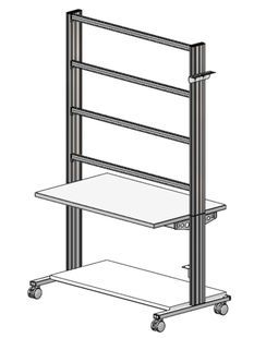
High-quality mobile experiment and demonstration trolley from the SybaPro range featuring aluminium table legs and low-level shelf.
This trolley is suitable for mounting under-table cabinets and is compatible with all add-ons and extensions in the SybaPro range.
It is supplied with one shelf, an angle bracket for attaching a PC and a cable holder.
Table top + Shelf:
- 30-mm table top made of highly compressed, multi-layer fine chipboard conforming to DIN EN 438-1
- Colour grey, RAL 7035, with 0.8-mm slightly textured laminate coating (Resopal) on both sides, conforming to DIN 16926
- Resistant to many chemicals and reagents including dilute acids and alkalis
- Resistant to heat, e.g. molten solder or heating at specific points such as by soldering tips or cigarette ends
- Frame with solid impact-resistant protective edging made of 3 mm thick RAL 7047 coloured plastic
- Coating and adhesive are PVC free
- Power strip with 6 outlet sockets mounted underneath the table top, lead and earthed plug
Frame:
- 2 extruded aluminium profiles with multiple grooves 1800 x 120 x 40 mm (WxHxD)
- 8 equally sized grooves in extruded aluminium profiles (3 on each side and 1 each on the front and back)
- Grooves accommodate standard industrial mountings
- 4 H-shaped aluminium profiles, 1150 mm, for 3-layer organisation of DIN A4 panels
- Space for extension of power supply duct
- Base made of rectangular tubing with 4 swiveling double casters, 2 of which have brakes
- Table frame made of tough combination of rectangular tubing around the full perimeter
- Acid-resistant epoxy-resin coating, 80 µm thick (approx.), colour RAL 7047
Cable holder:
- Width 200 mm with 12 cable slots to accommodate 48 x 4-mm safety measurement leads
PC attachment bracket:
- With 3 screw-on rubber stoppers, dimensions 65x65x114 mm approx. (top fixing for PC)
> The height of the cable holder and PC attachment bracket can be adjusted along the aluminium profiles
> For attachment to left or right, fastening materials included
> Acid-resistant epoxy-resin powder coating of thickness 80 µm approx., colour RAL 7047
Dimensions:
- Height of table top 760 mm
- 1250 x 1970 x 700 mm (WxHxD)
- The mobile experiment stand is supplied in kit form and needs to be assembled by customers themselves.
Monitor Holder for Flat Screen Monitor of Weight up to 15kg / 33lbs

Pivoting monitor holder for attachment to aluminium profiles of furniture in the SybaPro range. Allows a monitor to be placed in the optimum position so that work and experiments are less tiring.
- Pivoting arm with two-part joint
- Quick-lock for adjustment to any height on extruded aluminium profile
- VESA fastening 7.5 x 7.5cm
- Includes VESA 75 (7.5x7.5) - VESA 100 (10x10) adapter
- 2 Cable clips
- Adequate carrying capacity 15 kg / 33 lbs
- TFT monitor can be turned parallel to the table edge
- Separation can be adjusted to anywhere between 105 and 480 mm
Additionally included:
Cable management set for installing cables along the profiles of the aluminium lab system furniture in the SybaPro range, consisting of:
- 3 Cross cable blocks for front and rear grooves of aluminium profile
- 3 Cross cable blocks for side grooves of aluminium profile
- 12 Cable ties
- 4 Aluminium cover profiles for covering and enabling wires to be run along the grooves of an aluminium profile
Set of Leads for "Modular Engine Management"
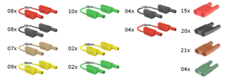
This set of 4-mm connecting leads has been specially assembled for the "Modular engine management: Common rail" training system, i.e. the actual colours and the lengths of the leads enhance the educational concept behind the training system itself. This makes it easier to distinguish between sensors, actuators and power supply. All the measurement leads and jumpers are special models which make it impossible to come into contact with any live electricity. To make measurements easy, all the jumpers have a single contact. In addition, the number of leads and jumpers provided is such that replacements are already available should any be lost. The content of the set in detail is as follows:
Jumpers
- 15 x Jumpers (red)
- 20 x Jumpers (black)
- 21 x Jumpers (brown)
- 04 x Jumpers (green)
Connecting leads
- 08 x Safety measuring leads (red, 50cm)
- 07 x Safety measuring leads (brown, 50cm)
- 08 x Safety measuring leads (black, 50cm)
- 10 x Safety measuring leads (green, 50cm)
- 09 x Safety measuring leads (yellow, 50cm)
- 02 x Safety measuring leads (green, 100cm)
- 02 x Safety measuring leads (yellow, 100cm)
Measuring leads
- 04 x Safety measuring leads (red, 150cm)
- 04 x Safety measuring leads (black, 150cm)