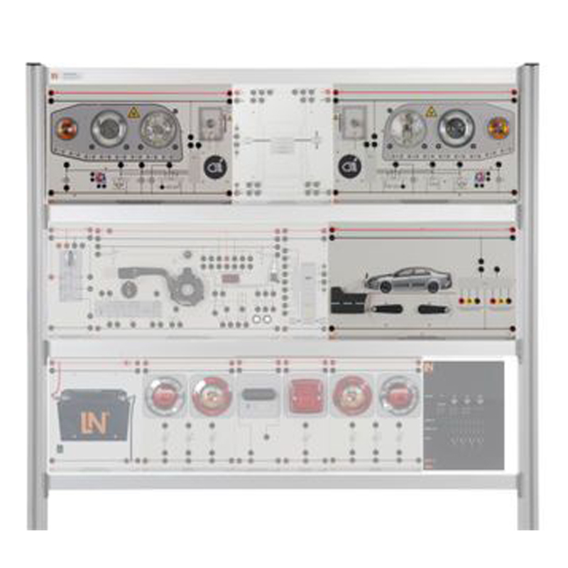
ALC 1.8 Xenon Trainer, LED and Daylight Driving Lights Trainer
Part No.: MPLCNL-ALC-1.8-Xenon-Trainer-LED-and-Daylight-Driving-Lights-Trainer
By means of various fault simulation switches, various faults which occur in practice can be activated on the LIN bus to help students gain essential diagnostic skills.
產品介紹
ALC 1.8 Xenon Trainer, LED and Daylight Driving Lights Trainer
You can expand any lighting installation employing a CAN bus by adding a modern lighting concept for the front headlights. Thanks to the special educational concept, this extension is the only way to truly explain the topics of xenon lighting, LED lights and daylight driving lights by means of a training system. The training system itself makes it possible for students to investigate the various types of lighting concept simultaneously and therefore to practically identify their features and differences. Furthermore, automatic height adjustment for the xenon lights is also included.
By means of various fault simulation switches, various faults which occur in practice can be activated on the LIN bus to help students gain essential diagnostic skills.
Supplement to Basic Set, Consisting of...
Ignition / Starter Switch
Safety ignition/starter switch with three switching levels and settings for energizing terminals 75, 15 and 50. Connections for the fuses are established via 4mm safety jacks, which can be bridged in an organized manner by means of compact jumpers for feeding from terminal 15 or 30. To facilitate an overview for students, the power supply installation is highlighted by means of a colour scheme according to DIN72551 at the board's upper and lower edges.
- Inputs and outputs: 4mm safety jacks
- Dimensions: 297 x 228 x 90 mm
- Weight: 0.8 kg
Xenon Headlights with Daylight Driving Lights (Right)
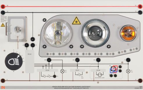
This modular panel is part of the "Xenon, LED and daylight driving lights" expansion set and represents the right-hand side of a vehicle's headlight installation. Apart from the lighting components the panel also includes a direction indicator, dipped and headlight beams and various safety sockets for making measurements. As well as the light cone adjustment built into the headlights, there is also an additional visual representation of such a system on the panel. By means of the lockable fault box, various simulated faults can be activated in the headlight system.
Lights:
- Dipped lights: xenon
- Headlights: LED
- Daylight driving lights: LED
Faults which can be activated:
- Wire break in parking light system
- Missing dimmer function for daylight driving lights
- Break in LIN bus
- Break in line to actuator motor
- Part of equipment set ALC 1.8
Xenon Headlights with Daylight Driving Lights (Left)
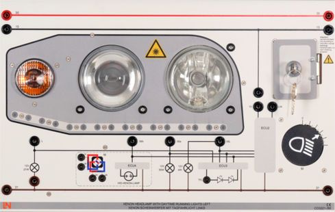
This modular panel is part of the "Xenon, LED and daylight driving lights" expansion set and represents the left-hand side of a vehicle's headlight installation. Apart from the lighting components the panel also includes a direction indicator, dipped and headlight beams and various safety sockets for making measurements. As well as the light cone adjustment built into the headlights, there is also an additional visual representation of such a system on the panel. By means of the lockable fault box, various simulated faults can be activated in the headlight system.
Lights:
- Dipped lights: xenon
- Headlights: halogen
- Daylight driving lights: LED
Faults which can be activated:
- Dipped lights and parking lights connected together
- Short to 12 V on LIN bus
- Short to ground on LIN bus
- Junction resistance in line to indicator
- Part of equipment set ALC 1.8
Automatic Headlights Height Adjustment
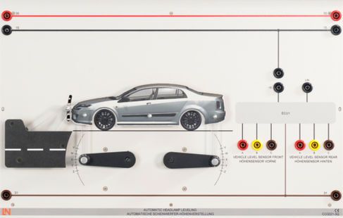
This modular panel allows the automatic height adjustment system for xenon headlights (CO3221-3M/3N) to be activated or controlled. The current level of the lights can be activated from the model of the vehicle, so that the actuator motors in the headlights can be made to respond directly. All connection and measuring points on the module are provided with 4-mm safety sockets.
Part of equipment set ALC 1.8
Media
Interactive Lab Assistant: Modern Automotive Light Systems - Xenon, LED and DRL

Light is technology
The lighting system in a vehicle is one of the most critical systems in terms of safety. It ensures that the driver of the vehicle can quickly observe events in the surroundings, even when it is dark, thus enabling safe and careful driving. Over the course of the last few years, lighting systems in vehicles have undergone important developments. Halogen lights are losing their importance and are increasingly being superseded by xenon and LED systems. These not only provide good lighting, but allow dynamic lighting functions to be implemented which greatly increase safety in traffic. However, front headlights are not only a key part of the safety aspect, they also play a key role in defining the look of a vehicle – in particular the daylight driving lights, which many well known manufacturers are now putting to use.
The training system "Modern lighting systems in vehicles – Xenon lights, LEDs and daylight driving lights" consists of various modular panels, which offer many possibilities for interaction and practical working with the CO3221 system. Furthermore, the accompanying multimedia course uses numerous animations to make the theory easily understandable and to present it in an attractive way. The experiments included interact with the hardware and thus ensure an in-depth and well-grounded understanding of the system, which can be directly applied in practice at vehicle repair workshops. Thanks to the built-in fault-finding system, various faults in the system can be activated, which also ensures the acquisition of essential diagnostic skills.
The course conveys the following contents:
- Basic terminology of lighting systems
- How xenon lights work
- How LED lights work
- Properties of light sources
- Advantages of xenon technology
- Advantages of LED technology
- Detailed description of daylight driving lights
- Introduction to "intelligent lighting systems" (adaptive forward light - AFL)
- Legal stipulations in Germany
- Handling xenon and LED lights
- Diagnostics on xenon and LED lighting systems
The hardware allows the following practical experiments to be carried out:
- Analysis of the system for automatic range adjustment (self-levelling) systems
- Measurements on a LIN bus
- Measurement of voltage and current on lighting components via 4-mm safety sockets
- Measurements on the servo motor for the automatic range adjustment system via 4-mm safety sockets
- Incorporation of the lighting system into an overall lighting system for the vehicle controlled via a CAN bus
- Activation of various faults to create intentional breakdowns in the system
Additionally Required
CAN/LIN Monitor
.jpg)
The CAN/LIN monitor allows bus protocols on a LIN bus, CAN bus or any serial bus to be recorded and investigated. Users are free to display the bus packets in binary or hexadecimal code. All activity on the respective bus is logged by the software and displayed in a list. Any command can be transmitted along the bus with the aid of a transmit function. Another key feature is the ability to display all bus levels graphically in a real-time diagram, where the individual sections of code are shown directly on a graphic. This is a particularly effective way to demonstrate the basic principles of bus communication and the differences between the various bus protocols.
The software has the following features:
- Visual display of bus protocol structure
- Option for displaying in binary or hexadecimal code format
- Recording of bus packets
- Transmission of bus packets
- Suitable for student experiments and demonstrations
- Simple to get working (via USB interface)
- Recording of CAN, LIN and serial bus packets
- Transmission of CAN, LIN and serial bus packets
- Display of identifiers
- Display of data lengths
- Display of timing periods
- User-configurable graphic interface
- All results and their display mode can be stored
- Detailed help integrated into the program
- Weight: 0.5 kg approx.
- Dimensions: 150 x 80 x 40 (L x W x H)
System requierments
- MS Windows 10 64bit
- Windows Version from 1803
CAN Lighting Interface
.jpg)
Control unit for controlling vehicle lighting components from the UniTrain-I card "CAN Node Front" via CAN bus or switching interface CO3216-2X
- Baud rate parameters can be configured
- Compatible with Low-Speed and High-Speed CAN buses (ISO 11898-2 and ISO 11898-3)
- Operating voltage: 12 V/13.8 V
- Outputs: 18 load outputs, max.7.5 A
- Bus outputs: 2-mm and 4-mm safety sockets
- Load outputs: 4-mm safety sockets
- Dimensions: 297 x 228 x 60 mm
- Weight: 1.1 kg
CAN Switching Interface
.jpg)
The CAN switching interface can be integrated into any existent, main lighting system, whose analog input signals are then converted by the interface into digital CAN messages. In combination with the CAN lighting interface, this makes it possible to set up a functional CAN node for the purpose of visualizing and measuring the fundamental parameters related to a CAN bus. The CAN messages are output via 2-mm and 4-mm safety sockets. A switch can be used to toggle the baud rate between low-speed bus and high-speed bus.
- Baud rate adjustable between 125 kbps and 1 mbps
- Compatible with low-speed and high-speed CAN buses (ISO 11898-2 and ISO 11898-3)
- Operating voltage: 12 V / 13.8 V
- Inputs: 4-mm safety sockets
- Outputs: 4-mm and 2-mm safety sockets
- Vehicle-specific terminal designations
- Visual indications of bus errors
- Continuous voltage supply via terminals 30 and 15 in the upper section
- Continuous ground via terminal 31 in the lower section
- Coloured screen print
- Dimensions: 297 x 114 x 60 mm
- Weight: 1.0 kg
UniTrain Interface with Virtual Instruments (Basic VI)
.jpg)
The UniTrain Interface is the central unit of the UniTrain system. It incorporates all inputs and outputs, switches, power and signal sources and measurement circuitry needed to perform experiments. The Interface is controlled via the connected PC.
Equipment:
- 32-bit processor with storage memory for measurements
- USB interfaces, transfer rate 12 Mbits/s
- WLAN/WiFi interface, 2.4 GHz, IEEE 802.11 b/g/n
- Simultaneous connection of any number of Experimenters via serial bus system
- High-quality designer casing with aluminium feet and surface-hardened Plexiglas front panel
- Suitable for accommodating in training panel frames for DIN A4 training panels
- Designed for connection of 2-mm safety measuring leads
- Multi-coloured LEDs for displaying status
- Adjustable analog output, +/-10 V, 0.2 A, DC – 5 MHz, via BNC and 2-mm sockets
- 4 Analog differential amplifier inputs with 10 MHz band width, safe for voltages up to 100 V, sampling rate 100 mega samples, 9 measuring ranges, memory depth 4 x 8 k x 10 bits, inputs via BNC (2 inputs) or 2-mm sockets (4 inputs)
- 2 Analog inputs for current measurement, overcurrent-protected up to 5 A, sampling rate 250 kilo samples, 2 measuring ranges, resolution 12 bits, connection via 2-mm sockets
- 3 variable analog outputs +/- 20V, 1 A, DC-150 Hz (requires CO4203-2B)
- 16-bit digital signal output, of which 8 bits are accessed via 2-mm sockets, TTL/CMOS, clock frequency 0 – 100 kHz, electric strength +/- 15 V
- 16-bit digital signal input, of which 8 bits are accessed via 2-mm sockets, memory depth 16 bit x 2 k, TTL/CMOS, sampling rate 0 – 100 kHz, electric strength +/- 15 V,
- 8 Relays, 24 V DC/1 A, of which 4 are accessed via 2-mm sockets
- Dimensions: 29.6 x 19 x 8.6 cm
- External power supply with wide range input 100-264 V, 47-63 Hz, output 24 V / 5 A
- Weight (including power supply): 2.1 kg
Virtual instruments (meters and sources):
- 2 x Voltmeter VIs, 2 x Ammeter VIs: AC, DC, 9 ranges, 100 mV to 50 V, true RMS, AV
- 1 x Power meter, 9 ranges, 100 mV to 50 V
- 1 x VI with 8 relays, 1 x Multimeter VI: multimeter display (optional LM2330, LM2331 or LM2322) in LabSoft
- 1 x 2-channel ammeter VI: AC, DC, 2 ranges, 300 mA and 3 A, TrueRMS, AV
- 1 x 2-channel voltmeter VI: AC, DC, 9 ranges, 100 mV to 50 V, TrueRMS, AV
- 1 2-/4-channel oscilloscope: band width 10 MHz, 25 time ranges, 100 ns/div to 10 s/div, 9 ranges 20 mV/div to 10 V/div, trigger and pre-trigger, XY and XT modes, cursor function, addition and multiplication function for 2 channels
- 1 x VI Spectrum Analyzer: 9 voltage ranges 100 mV to 50 V, input frequency range 3 Hz to 1 MHz, time domain display
- 1 X VI Bode-Plotter: 9 voltage ranges 100 mV to 50 V, frequency range 1 Hz - 5MHz, time domain display and locus diagram
- 1 x Adjustable DC voltage VI 0 - 10 V
- 1 x Function generator VI: 0.5 Hz - 5 MHz, 0 - 10 V, sine, square, triangular,
- 1 x Arbitrary generator VI, 1 x Pulse generator VI
- 1 x VI with 16 digital outputs, 1 x VI with 16 x digital inputs, 1 x VI with 16 digital input/outputs. Display modes: binary, hex, decimal and octal numerals
- 1 x Three-phase power supply VI, 0 - 150 Hz, 0 - 14 Vrms, 2 A (requires CO4203-2B)
- 1 x Adjustable DC power supply VI, 3 x (-20 V - +20 V), 2 A (requires CO4203-2B)
- 1 x Three-phase power supply VI with additional phase-shift and clock rate adjustment (requires CO4203-2B)
Includes:
- Interface
- Power supply
- Power lead
- USB cable
- CD with basic software
- Operating manual
System requirements:
- Personal computer with Windows Vista, Windows 7, Windows 8, Windows 8.1, Windows 10 (32 or 64 bit)
- CD-ROM drive for installing software
- USB port for connection to Interface
UniTrain Measurement Accessories, Shunts and Connection Cables
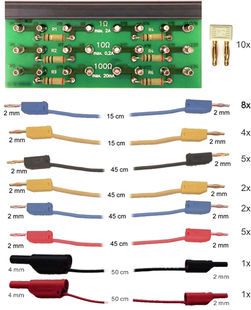
Shunt resistors on a PCB, for current measurement using the analog inputs of the UniTrain system.
- 6 Shunt resistors: 2 x 1 ohm, 2 x 10 ohm, 2 x 100 ohm
- Screen print of symbols for identifying resistors, the voltage taps and current inputs
- 24 x 2-mm sockets
- Dimensions: 100 x 40 mm
Set of connection cables 2 mm (28 pcs) for UniTrain consisting of:
- 8 x connection leads 2 mm, 15 cm, blue
- 4 x connection leads 2 mm, 15 cm, yellow
- 5 x connection leads 2 mm, 45 cm, black
- 2 x connection leads 2 mm, 45 cm, yellow
- 5 x connection leads 2 mm, 45 cm, red
- 2 x connection leads 2 mm, 45 cm, blue
- 1 x safety adapter lead 4 mm to 2mm, 50 cm, black
- 1 x safety adapter lead 4 mm to 2mm, 50 cm, red
- 10 x 2-mm connector plugs / Plug spacing 5 mm, white
Digital Current Probe for Current up to 300 A (AC/DC)
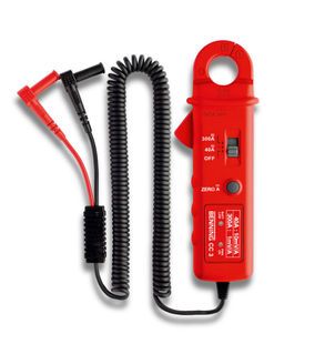
Using this simple-to-operate current measuring probe, it is easy to measure current quickly and safely over a range from 1 - 300 amps. The probe can be used to measure both direct current and alternating current. The current probe can be connected directly to your UniTrain-I Interface by means of 4-mm safety leads. This greatly increases the range over which the UniTrain system can carry out measurements.
Technical data:
- Base accuracy: 1%
- Current range, AC/DC: 1A - 300A
- Distance between jaws max.: 25 mm
- Measurement category: CAT III 600V
Adapter BNC/2x4 mm Safety Sockets, Insulated
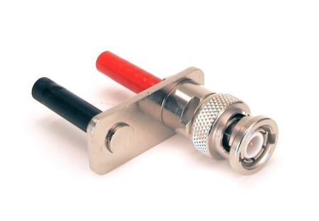
Adapter plug for connecting BNC connector to 4-mm safety sockets
- BNC plug, 2 insulated 4-mm safety sockets
- Contact rings and sockets for internal pin of BNC connector are made of gilded brass
- CAT II/1000 V
Power Supply
Power Supply, 13.5 V, 45 A
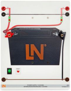
The "Power supply" module is part of ´various training systems including the "Modular engine management" system. It provides power to various components in a similar to the way they are supplied in practice in a real engine by means of a 12 V battery. The module employs a 600 watt power unit which can supply a maximum current of 45 A at 13.5 V between its screw terminals. To protect the training system, a maximum current of 30 A can be tapped via the 4-mm safety sockets. This protective function is implemented by electronic monitoring of the 4mm safety sockets. Thanks to the high-resolution printing on the front panel, the module can immediately be identified as a typical car battery.
Technical highlights:
- Stable on-board network voltage of 13.5 volts
- Automatic cut-out without fuses
- Short-circuit protection
- Typical appearance of a vehicle battery thanks to high-resolution printed image of a starter battery
- Maximum current: 45 A
Technical details:
- Operating voltage: 90-264 V AC (47-63 Hz)
- Dimensions: 297 x 227 x 180 mm (HxWxD)
- Weight: 1.6 kg
Media
Interactive Lab Assistant: Automotive Lighting

The CarTrain course "Lighting for cars and commercial vehicles" represents the perfect supplement to the “Vehicle lighting” set. It explains in detail how the system is put into operation along with all the essential theoretical background regarding lighting in cars and commercial vehicles. Trainees learn how to work with the circuit diagrams for a lighting system and how to use them logically and efficiently as part of a maintenance or diagnostic procedure. Apart from putting a lighting system into operation, various diagnostic skills for locating problems are learned and various measurements are made on the system itself. Each section is concluded by a test of knowledge.
Sets:
The course makes reference to the following sets:
- Headlights (ALC 1.1)
- Additional lighting and signalling systems (ALC 1.2)
- Trailer lighting (ALC 1.3)
- CAN-bus enhancement (ALC 1.6)
- On-board network enhancement including daytime running lights (ALC 1.7)
Course contents:
The course features the following training contents:
- Use of circuit diagrams
- Printable circuit diagram for the entire lighting system
- Use of workshop order contracts
- Conventional switching and CAN-based control
-
Comprehensive handling of lighting equipment
- Dipped headlights
- Headlights
- Fog lamps
- Daytime running lights
- Parking lights
- Sidelights
- Brake lights
- Rear lights
- Rear fog lamps
- Reversing lights
- Indicators
- Licence plate illumination
- Interior lights
- Trailer lighting
- Headlight configuration
- Horn and light flashing system
- Troubleshooting (circuit diagram)
Please note that the "Static cornering lights" set is described in a separate course.
Measuring Instruments
Adapter BNC/2x4 mm Safety Sockets, Insulated

Adapter plug for connecting BNC connector to 4-mm safety sockets
- BNC plug, 2 insulated 4-mm safety sockets
- Contact rings and sockets for internal pin of BNC connector are made of gilded brass
- CAT II/1000 V
Test Lamp

Vehicle voltage tester. Due to its small current consumption of 1.5 mA, the CAR-CHECK tester is particularly well suited to finding faults with electronic components. Conventional test lamps often cause damage to these. Polarity indication via two LEDs.
- Nominal voltage range: 3...48 V
- Length of lead: 150 cm
- Weight: 0.2 kg
Multi 18 Digital Multimeter
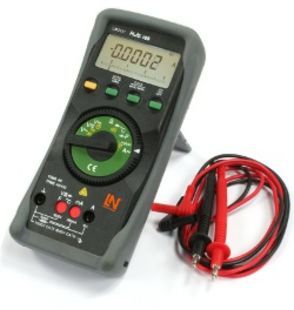
Universal precision lab multimeter and temperature meter with IR interface for high-quality, universal measurement and testing in educational settings, power plants, process control installations etc.
- 4¾-digit multimeter; resolution: ±31,000 digits
- Measurement classification CATII-1000 V
- Can be connected to UniTrain-I system via IR interface
- Real-time RMS measurement TRMS
- Voltage and current measuring ranges (AC and DC): 300 mV-1000 V; 300 µA-10 A
- Decibel measurement
- Resistance ranges: 300 ohm-30 M ohm
- Capacitance measuring range 3 nF to 10,000 µF
- Frequency measuring range up to 100 k Hz, counter and stopwatch
- Special functions: ° C for temperature measurements using PT100/1000 thermocouple
- Continuity and diode testing
- Automatic range selection and battery shut-off, min./max. and data hold function
- Protection against high currents in the mA range for nominal voltage of 1000 V
- Safety fuse for all current measurement ranges (up to 10 A)
- Display with bar chart and backlighting
- Includes protective sleeve, measuring leads, 2 x spare fuses, 9 V battery, calibration certificate
Digital Dual Trace Storage Oscilloscope W. Colour Display, Incl. Probes 30 MHz
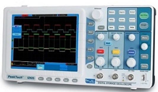
Digital storage oscilloscope with colour LCD display, high resolution, backlighting and USB port for transmission of large quantities of data at high data rates.
Technical data:
- Bandwidth 30 MHz/125 MS/s
- Maximum input voltage 400 V
- 8" TFT colour display
- USB port, USB flash disk, LAN, VGA
- Cursor function
- Five automatic measurement functions, storage and retrieval of traces
- Edge and video trigger function
- Safety specifications: EN 61010-1
- Supplied with accessories: 2 probes, mains lead, USB cable, software CD
- Dimensions: 350x157x120 mm (WxHxD)
- Weight: 1.0 kg
Accessories
Set of Circuit Breakers for Vehicles (10A/15A)
.jpg)
- Single-pole thermal circuit breaker for vehicles, slim format with coloured manual trip switch
- Reliable tripping response thanks to snap-action trip switch
- Tamper-proof rip interlock to prevent reactivation of the circuit till the fault is rectified
- Plugs into low-profile vehicle fuse box
- Nominal voltage 12V
The set comprises the following components:
- 1x 10A vehicle circuit breaker
- 1x 15A vehicle circuit breaker
Set of 4-mm Measurement Leads with Safety Connection Leads for ALC (Complete)
.jpg)
The set of leads is intended for wiring the entire lighting system of a vehicle and covers all additional adaptive lighting control (ALC) equipment options. The set of leads consists of the following components:
Safety connecting leads:
- 1x 4-mm safety connecting leads, colour: yellow/length: 50 cm
- 1x 4-mm safety connecting leads, colour: blue/length: 50 cm
- 10x 4-mm safety connecting leads, colour: red/length: 25 cm
- 05x 4-mm safety connecting leads, colour: red/length: 75 cm
- 10x 4-mm safety connecting leads, colour: black/length: 25 cm
- 30x 4-mm safety connecting leads, colour: black/length: 75 cm
- 15x 4-mm safety connecting leads, colour: black/length: 100 cm
Safety connection plugs:
- 20x safety connection plugs, colour: red
- 17x safety connection plugs, colour: brown
- 45x safety connection plugs, colour: black
Mobile Aluminum Experiment Stand, 3 Levels, Power Strip with 6 Sockets, 49"x28"x79" WxDxH (1250x700x1995mm)
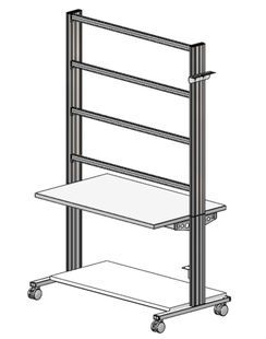
High-quality mobile experiment and demonstration trolley from the SybaPro range featuring aluminium table legs and low-level shelf.
This trolley is suitable for mounting under-table cabinets and is compatible with all add-ons and extensions in the SybaPro range.
It is supplied with one shelf, an angle bracket for attaching a PC and a cable holder.
Table top + Shelf:
- 30-mm table top made of highly compressed, multi-layer fine chipboard conforming to DIN EN 438-1
- Colour grey, RAL 7035, with 0.8-mm slightly textured laminate coating (Resopal) on both sides, conforming to DIN 16926
- Resistant to many chemicals and reagents including dilute acids and alkalis
- Resistant to heat, e.g. molten solder or heating at specific points such as by soldering tips or cigarette ends
- Frame with solid impact-resistant protective edging made of 3 mm thick RAL 7047 coloured plastic
- Coating and adhesive are PVC free
- Power strip with 6 outlet sockets mounted underneath the table top, lead and earthed plug
Frame:
- 2 extruded aluminium profiles with multiple grooves 1800 x 120 x 40 mm (WxHxD)
- 8 equally sized grooves in extruded aluminium profiles (3 on each side and 1 each on the front and back)
- Grooves accommodate standard industrial mountings
- 4 H-shaped aluminium profiles, 1150 mm, for 3-layer organisation of DIN A4 panels
- Space for extension of power supply duct
- Base made of rectangular tubing with 4 swiveling double casters, 2 of which have brakes
- Table frame made of tough combination of rectangular tubing around the full perimeter
- Acid-resistant epoxy-resin coating, 80 µm thick (approx.), colour RAL 7047
Cable holder:
- Width 200 mm with 12 cable slots to accommodate 48 x 4-mm safety measurement leads
PC attachment bracket:
- With 3 screw-on rubber stoppers, dimensions 65x65x114 mm approx. (top fixing for PC)
> The height of the cable holder and PC attachment bracket can be adjusted along the aluminium profiles
> For attachment to left or right, fastening materials included
> Acid-resistant epoxy-resin powder coating of thickness 80 µm approx., colour RAL 7047
Dimensions:
- Height of table top 760 mm
- 1250 x 1970 x 700 mm (WxHxD)
The mobile experiment stand is supplied in kit form and needs to be assembled by customers themselves.
Monitor Holder for Flat Screen Monitor of Weight up to 15kg / 33lbs
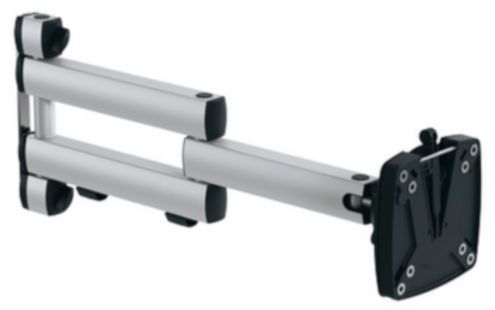
Pivoting monitor holder for attachment to aluminium profiles of furniture in the SybaPro range. Allows a monitor to be placed in the optimum position so that work and experiments are less tiring.
- Pivoting arm with two-part joint
- Quick-lock for adjustment to any height on extruded aluminium profile
- VESA fastening 7.5 x 7.5cm
- Includes VESA 75 (7.5x7.5) - VESA 100 (10x10) adapter
- 2 Cable clips
- Adequate carrying capacity 15 kg / 33 lbs
- TFT monitor can be turned parallel to the table edge
- Separation can be adjusted to anywhere between 105 and 480 mm
Additionally included:
Cable management set for installing cables along the profiles of the aluminium lab system furniture in the SybaPro range, consisting of:
- 3 Cross cable blocks for front and rear grooves of aluminium profile
- 3 Cross cable blocks for side grooves of aluminium profile
- 12 Cable ties
- 4 Aluminium cover profiles for covering and enabling wires to be run along the grooves of an aluminium profile
Additionally Recommended
Protection Cover for Three-Level Experiment Trolleys

Dust cover for three-level experiment trolleys
- For protecting equipment from dust and damp
- For keeping equipment out of sight (the cover must not be transparent, so is therefore opaque)
- Colour: matt dark grey with printed LN logo in orange)
- Material: nylon fabric with polyurethane coating
- High resistant to tearing, impregnated to be washable and waterproof
Trolley for Measurement Leads (Max. Length 100cm), for up to 320 (2x 160) Measurement Leads (100cm)

SybaPro mobile trolley for measurement leads
- Main pillar made of 35-mm extruded aluminium profile with four-groove symmetry
- 8 Identical grooves (3 on each side + 1 on each edge)
- Grooves accommodate industrially standardised mountings
- 4 Steerable casters, 2 with brakes
- 4 Cable racks, each with grooves to accommodate 40 leads
- Suitable for up to 320 (2x160) measurement leads
- Base frame with four legs and rigid steel cable racks featuring acid-proof epoxy-resin powder-coating approximately 80 µm thick, colour RAL 7047
- Dimensions: 640x400x1400 mm (WxDxH)