CAN-Bus Tester 2
Part No.: MPGE-CAN-Bus-Tester-2
A widely used measuring device for control of bus parameters
產品介紹
Possibilities
The CAN-Bus Tester 2 is a widely used measuring device for control of bus parameters. The success story starts already in the year 2002 with the first model. The hardware was completely redesigned in version 2. The corresponding software is still developed and has been enhanced with extensive updates.
Check the setup of the bus before you switch on with the bus wiring test, measure under running conditions down on the physical layer and analyses data of the nodes with the protocol monitor. The longtime monitor shows scattered errors and creeping signal loss.
The trigger output makes it possible to show data from only one node of the bus.
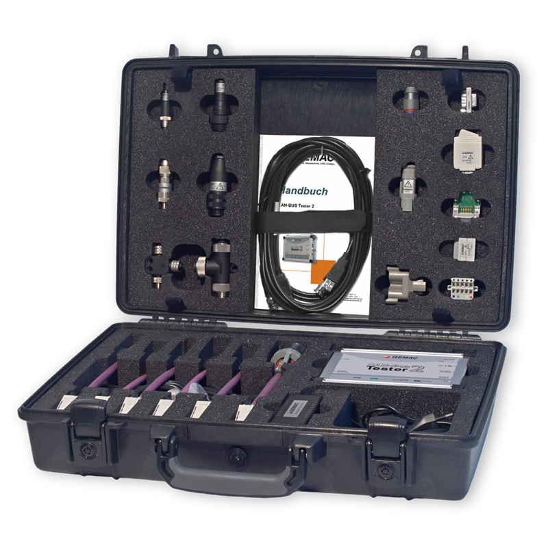
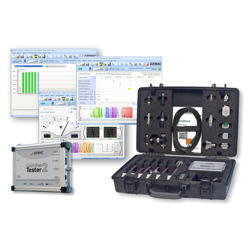
The great box contents within the service case with big adapter set make it possible to use the device out of the box in many environments. You can save your measurements and print a status protocol directly from the software.
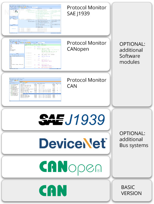
License Model
In the basic configuration, the CAN-Bus Tester 2 is enabled for bus system CAN. You can do all physical measurements within this system.
Additional licenses are offered to the systems CANopen, DeviceNet and SAE J1939. With them, it is much easier to assign the messages to the real nodes.
The optional protocol monitor is for logical bus analysis in the bus systems CAN (transmit/receive), CANopen (receive) and SAE J1939 (receive).
The user software is free to download and use, only for measurements with the CAN-Bus Tester 2 it has to be unlocked.
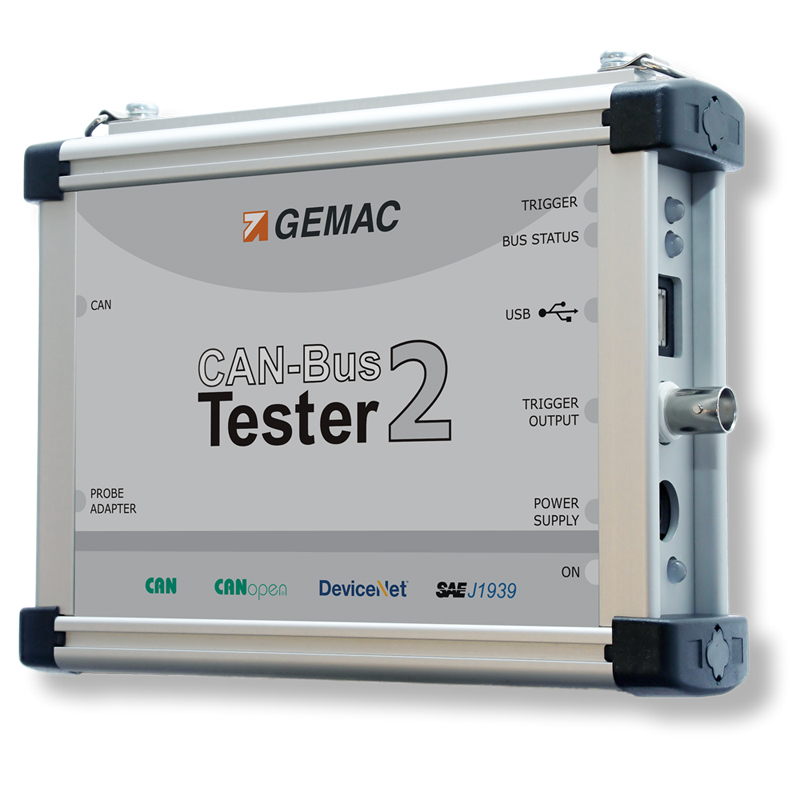
Connections
-
Power Supply
- The device works with 9 – 36 V. Only for the Bus Wiring test min. 24 V is needed.
-
USB Port
- Connect your Windows PC or laptop here.
-
CAN and CAN probe port
- Two 9‑pin D‑Sub ports are for connection to the bus and for probes
-
Trigger Output
- For further measurements with a digital storage oscilloscope, the CAN-Bus Tester 2 can be used as the trigger source.
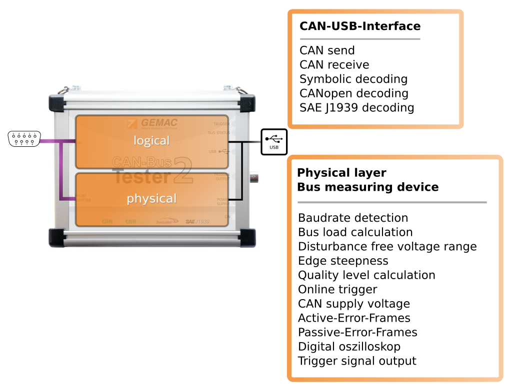
Two Devices in one
The CAN-Bus Tester 2 is basically a 2‑in‑1 device. One part is responsible for the extensive measurements on the physical level. The 64-fold sampling of each individual bit makes detailed evaluation possible.
The other part is a CAN-to-USB interface for comprehensive protocol analysis. Both parts of the device can work independently of each other or simultaneously and together.
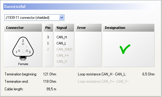
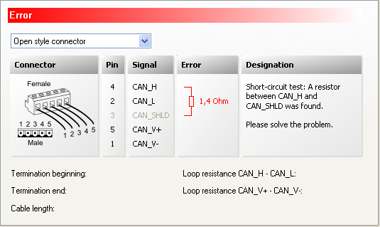
Bus Wiring Test
With the wiring test, it is possible to determine line short-circuits, line breaks, the bus termination, the loop resistance of the CAN line and the CAN power supply line and the overall line length.
To ensure correct bus cabling, it is recommended to perform the wiring test at the beginning of any plant measurements.
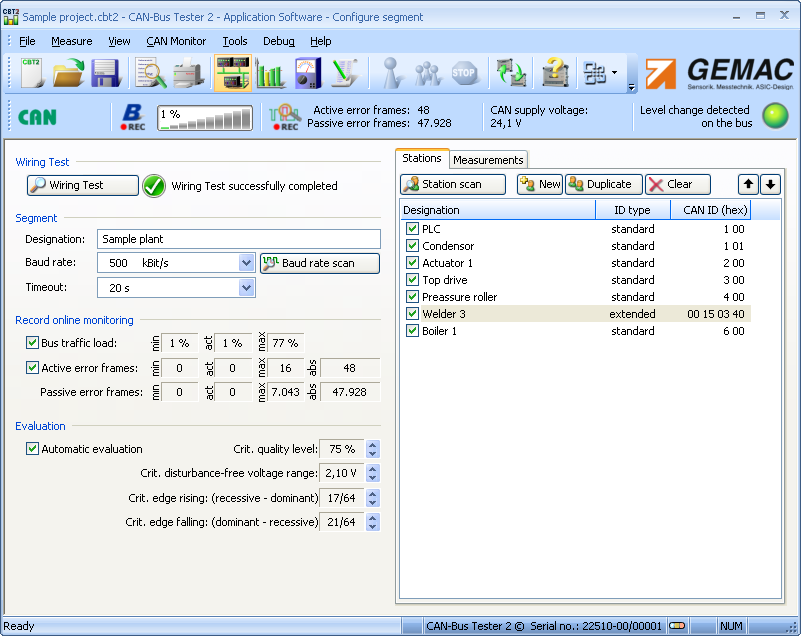
Node Measurement
Connect the CAN-Bus Tester 2 to your bus line. You should see a green led on your display, showing that there is data traffic.
First, start the baud rate scan, then scan for nodes. All messages on the bus are now received and analyzed, the nodes with their ID are listed. Name the nodes if you want for a better overview.
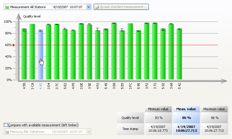
With the measurement “all stations view” you get an overview of the quality levels of the signals. The bar diagram makes it easy to compare. At continuous mode, you will additionally see the min/max values. You can easily compare to a saved measurement.
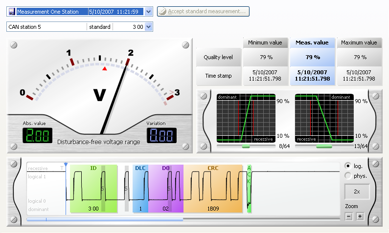
The measurement “one station’s view” shows the single values of one node and shows a physical and logical decoded oscillogram. Quality level, edge steepness and disturbance-free voltage range are the three showed measurands. By starting a continuous measurement you will also see the min/max of quality level and the variation of the disturbance-free voltage range.
Online Monitor
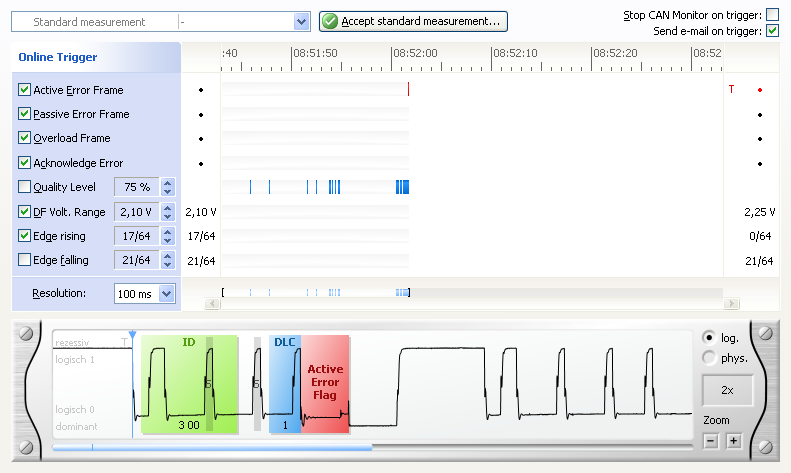
This measurement runs continuously and compares with given thresholds. If it overruns the threshold the error will be registered. In the single measurement mode, it stops and the faulty message is showed in the oscilloscope view. In continuous mode, the error is marked in a timing diagram. So you show when your threshold was overruled or if an error frame has occurred.
The observed values are
- Active-Error /Passive-Error Frames
- Overload Frames
- Acknowledge Error
- General quality level (0 … 100 %)
- Disturbance-free voltage range (minimum noise-free differential voltage)
- Edge steepness (worst rising and falling edge of a message)
Additionally, to this logical and physical measurements, the CAN-Bus Tester 2 is continuously determining bus traffic load, bus status and the optional CAN supply voltage.
The software can be adjusted in a way, that a simultaneously running Receive in the protocol monitor is stopped in case of an error. So it is easier to analyze that data traffic that was on the bus before the error occurred.
Technical Data
| General parameters and overview of functions | |
|---|---|
| Bus Systems | CAN (ISO11898‑2), CANopen (CiA301), DeviceNet (EN 50325 – 2), SAE J1939 |
| Bit Sampling | 64-fold, 10,240 sampling points |
| Bit timing | Adjustable BTL cycles (tq), sample point and resynchronization jump width (SJW) |
| Supported Baud Rates |
Depending on bus system : 10 ; 20 ; 50 ; 100 ; 125 ; 250 ; 500 ; 800 ; 1000 kbit/s
Additionally user-defined : 5 ; 33.3 ; 62.5 ; 75 ; 83.3 ; 200 kbit/s
Automatic detection via baud rate scan
|
| List of Stations |
Automatic detection via Station scan
Designation, CAN ID, ID type, Node ID, MAC ID, Source address,
can also be entered manually
|
| List of Measurements |
Possibility to measure at different measuring points and at different times
Sorting by measurement type, measuring point and measurement time
|
| Quality Level |
Value representing the signal quality (0 …100%)
The minimum value and maximum values saved timestamp
|
|
Disturbance-free Voltage Range and edges |
Disturbance-free voltage range (typ. ‑0.75 … 3 V, resolution 50 mV)
Edge steepness (falling and rising, specified in 1/64th of the bit width)
The minimum value and maximum values saved
|
| Oscilloscope Display |
Trigger on message frames with the specified ID, trigger position can be set
Frame analysis and full frame recording
Decoding according to the protocol (CAN, CANopen, DeviceNet, SAE J1939)
Zoom (six stages) |
| Online Trigger |
Real-time monitoring of the bus for logical and physical errors
Resolution can be set (10 ms … 1 min)
Oscilloscope display and e‑mail notification on triggers
|
| Automatic Evaluation |
Limit value settings and measured-value evaluation according to :
|
| Bus Status | Bus traffic detection (display : dominant, recessive, not defined, bus traffic) |
| Bus Traffic Load |
Permanent display of the bus traffic load (0 … 100%), Minimum and maximum
values saved |
| Error Frames |
Constant display of detected frame errors
Distinction between active and passive error frames (0 … >50,000)
|
| Protocol Monitor |
CAN : Reception of CAN message frames incl. filtering, Transmission of CAN
message frames and sequences (message lists)
CANopen : Interpretation of all CAN messages according to the CANopen spec
as SDOs, PDOs, NMT‑, Heartbeat‑, Emergency‑, Sync- and Timestamp
(CiA301, CiA302, CiA305, CiA401, CiA402, CiA404, CiA406, CiA408, CiA410,
upgradeable) |
| Test Record |
Comprehensive, configurable measuring and test record on DIN A4 :
|
| Export Function |
Measuring data as a configurable CSV file
Graphical measured-data representation as a configurable bitmap (.bmp,.jpg,.png)
|
|
Firmware and FPGA Configuration |
can be updated via USB |
| CE Conformity | |
|---|---|
| Equipment Safety | EN 60950 – 1:2006/A1:2010 |
| EMC | |
|
Low-frequency Interference Emission |
EN 61000 – 3‑2:2006/A1:2009/A2:2009 |
|
High-frequency Interference Emission |
EN 55022:2006/A1:2007 |
| Interference Immunity | EN 61000 – 6‑2:2005/AC:2005 |
| Electrical Parameters | |
|---|---|
| Power Supply | Via the supplied wide-range power supply (9 … 36 V DC) |
| Current Consumption | 0.55 … 0.15 A |
|
Measuring of the Differential Voltage |
typ. ‑0.75 V … 3.00 V |
|
Measuring of the Loop Resistances |
typ. 0 Ω … 800 Ω |
|
Measuring of the Cable Length |
typ. 0 m … 500 m
for a signal runtime of : 4.5 ns/m for CAN/CANopen/SAE J1939, 4.3 ns/m for DeviceNet
|
|
Measuring of the CAN Supply Voltage |
0 … 36 V |
|
Potential Difference Between the Connections CAN bus, USB and oscilloscope |
50 V DC (or 71 V AC) |
| Trigger Output for the Oscilloscope | BNC socket, electrically isolated, H pulse, approx. 2 bits wide, level approx. 5 V |
| Mechanical Parameters | |
|---|---|
| Supply Voltage Connection | Extra-low voltage socket |
| CAN Connection | 2 x 9‑pin D‑Sub connector |
| PC Connection | Self-powered device to USB Specification 1.1, electrically isolated |
|
Trigger Output for Oscilloscope |
BNC socket, electrically isolated |
| Housing | Aluminum sheet housing |
| Temperature Range |
Operation : 5 °C … 40 °C
Storage : ‑20 °C … 60 °C
|
| Humidity |
Operation : 20 % … 80 % (non-condensing)
Storage : 20 % … 80 % (non-condensing)
|
|
Degree of Protection of the Housing |
IP20 to EN 60529 |
| Dimensions (Device /Case) | 170 mm x 134 mm x 40 mm /504 mm x 354 mm x 119 mm |
| Weight (Device /Case) | Approx. 600 g /Approx. 5000 g |
Warning :
The CBT2 is a Class A device. Such devices can cause interference in residential areas. In this case, the plant operator can be required to take appropriate measures and to bear the costs of such measures.
Order Information
| Product | Description |
GEMAC order number / shoplink |
|---|---|---|
| Basic set | ||
| CAN-Bus Tester 2 |
CAN-Bus Tester 2 – basic version
Bus system : CAN
complete delivery contents of CAN-Bus Tester 2
|
PR-22517 – 10 |
| Licenses for optional bus systems (physical measurements) | ||
| CANopen | License Key for bus system CANopen | SW-22517 – 01 |
| DeviceNet | License Key for bus system DeviceNet | SW-22517 – 02 |
| SAE J1939 | License Key for bus system SAE J1939 | SW-22517 – 03 |
| Licenses for optional Protocol monitor | ||
| CAN Transmit, CAN Receive | License key for protocol monitor CAN (transmit/receive) | SW-22517 – 10 |
| CANopen receive | License key for protocol monitor CANopen (receive) | SW-22517 – 11 |
| SAE J1939 receive | License key for protocol monitor SAE J1939 (receive) | SW-22517 – 12 |
| Optional accessory for more country versions | ||
| Mains power cable Australia | Mains power cable Australia for Adapter AC/DC |
KB-00093 – 03 upon request |