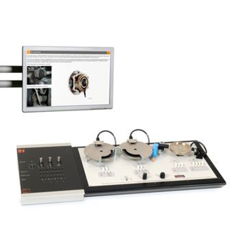
Wheel speed sensor system
Part No.: MPLCNL-Wheel-speed-sensor-system
The wheel speed sensors are used to measure the speed of the individual wheels and transmit this data to the ABS control unit, for example.
Product Description
Wheel Speed Sensor System
Traffic congestion continues to grow as do the number of more and more powerful motor vehicles entering the marketplace; these are just two features affecting the current situation on the road. This development is posing ever greater demands on both people and vehicles. While it may be more complicated to influence the “human” factor, there have been a host of so-called “driver assistance systems " integrated into the motor vehicle.
Especially in the area of braking systems and stability management systems, technical developments have advanced a long way. Systems like ABS and ESP have long become standard equipment in new vehicles. In many cases the customer can additionally choose radar-assisted automatic cruise control or adaptive steering systems for example. All of these systems have one thing in common; they need to have the vehicle's speed or the rotating speed of the individual wheels as input variables.
To achieve this, wheel speed sensors are used to measure the speed of the individual wheels and transmit this data to the ABS control unit, for example. Since this sensor technology has also continued to advance, it is necessary to understand how the various systems differ and to learn system-neutral diagnostics strategies.
List of Articles
UniTrain: Wheel Speed Sensor Technology
The way wheel speed signals are recorded has undergone drastic changes in recent years. The mechanical pulse generator ring has been replaced in many motor vehicles by a magnetic encoder. This has also led to totally new ways of diagnosing electrical signals and to new methods for inspecting mechanical components.
With the "wheel speed sensor technology" training system it should be possible to compare tried and trusted techniques in the form of inductive-type and Hall effect sensors directly with magneto-resistive sensors. It is also possible to carry out a mechanical inspection of the pulse generator ring and the magnetic encoder in the training system itself.
Includes
- “Wheel speed sensor“ board
- Resistor, 22 Ω
- Resistor, 1 kΩ
- Testing card
- Long measurement leads
- Labsoft browser, course software and additional virtual instruments
Components of the experiment hardware:
- Three electric traction motors
- Measurement sockets for on-board network voltage
- 4 control units available for experimenting thanks to measurement sockets for input and output signal processing
- Ignition switch
- Selection switch for individual or shared drive motor operation
- Continuous speed setting
- Speed indicator
- 2 Magneto-resistive sensors
- 1 Inductive-type sensor
- 1 Hall effect sensor
- 1 Pulse generator ring
- 2 Magnetic encoders
- 2 Cover plates
- Fault simulation circuits
Training contents:
- Purpose and application of wheel speed sensors
- Design and function of inductive-type sensors
- Design and function of Hall effect sensors
- Design and function of magneto-resistive sensors
- Mechanical check of pulse generator ring
- Mechanical check of magnetic encoder
- Conducting measurements and diagnosis of inductive-type sensors
- Conducting measurements and diagnosis of Hall effect sensors
- Conducting measurements and diagnosis of magneto-resistive sensors
- Changing wheel bearings with magnetic encoders
- Reading and understanding circuit diagrams
- Understanding workshop orders
- Developing diagnostic strategies
-
Applying a diagnostic function
- Reading out fault memory using a diagnostics unit
- Documenting troubleshooting
-
Repair methods and customer consultation
- Selection of repair measures in accordance with manufacturing specs
- Working with replacement part numbers
- Repercussions of faults commonly occurring in practice
- Switching on simulated faults for practice in troubleshooting
- Course duration 10 h approx.
Operating voltage:
- 12-15 V DC
Mains voltage:
- 100-240 V AC, 50-60 Hz
Dimensions/weight:
- 450x275x125 mm (length x width x height)
- 3.3 kg
Additionally Required
The UniTrain-I system is a computer-based training and experimentation system for vocational and further training and education in the areas of basic and advanced electrical engineering and electronics. Its multimedia courses combine cognitive and hands-on (haptic) training units into a comprehensive unified concept, specifically enabling students to acquire skills in the handling of equipment. Starting with basic courses and advancing to cover a huge variety of electrical engineering and electronics topics, a wide range of multimedia courses is available for study in school or in professional and advanced training courses. The UniTrain-I system is completely self-contained and can be used anywhere at any time. The multimedia learning environment the system provides high degrees of motivation, and maximum learning effectiveness in laboratories, at work or at home. It thus becomes a guarantor for effective and efficient study. Access to the multimedia courses and control of virtual instruments and experiment hardware is provided by LabSoft, the system's open experiment platform. The courses teach the theoretical building blocks and provide experiments to be carried out using the course-specific experiment hardware. The intelligent measurement interface supplies the analog and digital measuring and control I/O and represents, in combination with the system's virtual instruments, a high quality item of laboratory equipment. In addition, students' progress can be monitored and electronically documented on the basis of fault finding experiments with faults simulated by the hardware as well as tests of knowledge. The electrical and electronic circuits needed for the experiments are connected to the system with the aid of an Experimenter module.
UniTrain Interface with Virtual Instruments (Basic VI)
(3).jpg)
The UniTrain Interface is the central unit of the UniTrain system. It incorporates all inputs and outputs, switches, power and signal sources and measurement circuitry needed to perform experiments. The Interface is controlled via the connected PC.
Equipment:
- 32-bit processor with storage memory for measurements
- USB interfaces, transfer rate 12 Mbits/s
- WLAN/WiFi interface, 2.4 GHz, IEEE 802.11 b/g/n
- Simultaneous connection of any number of Experimenters via serial bus system
- High-quality designer casing with aluminium feet and surface-hardened Plexiglas front panel
- Suitable for accommodating in training panel frames for DIN A4 training panels
- Designed for connection of 2-mm safety measuring leads
- Multi-coloured LEDs for displaying status
- Adjustable analog output, +/-10 V, 0.2 A, DC – 5 MHz, via BNC and 2-mm sockets
- 4 Analog differential amplifier inputs with 10 MHz band width, safe for voltages up to 100 V, sampling rate 100 mega samples, 9 measuring ranges, memory depth 4 x 8 k x 10 bits, inputs via BNC (2 inputs) or 2-mm sockets (4 inputs)
- 2 Analog inputs for current measurement, overcurrent-protected up to 5 A, sampling rate 250 kilo samples, 2 measuring ranges, resolution 12 bits, connection via 2-mm sockets
- 3 variable analog outputs +/- 20V, 1 A, DC-150 Hz (requires CO4203-2B)
- 16-bit digital signal output, of which 8 bits are accessed via 2-mm sockets, TTL/CMOS, clock frequency 0 – 100 kHz, electric strength +/- 15 V
- 16-bit digital signal input, of which 8 bits are accessed via 2-mm sockets, memory depth 16 bit x 2 k, TTL/CMOS, sampling rate 0 – 100 kHz, electric strength +/- 15 V,
- 8 Relays, 24 V DC/1 A, of which 4 are accessed via 2-mm sockets
- Dimensions: 29.6 x 19 x 8.6 cm
- External power supply with wide range input 100-264 V, 47-63 Hz, output 24 V / 5 A
- Weight (including power supply): 2.1 kg
Virtual instruments (meters and sources):
- 2 x Voltmeter VIs, 2 x Ammeter VIs: AC, DC, 9 ranges, 100 mV to 50 V, true RMS, AV
- 1 x Power meter, 9 ranges, 100 mV to 50 V
- 1 x VI with 8 relays, 1 x Multimeter VI: multimeter display (optional LM2330, LM2331 or LM2322) in LabSoft
- 1 x 2-channel ammeter VI: AC, DC, 2 ranges, 300 mA and 3 A, TrueRMS, AV
- 1 x 2-channel voltmeter VI: AC, DC, 9 ranges, 100 mV to 50 V, TrueRMS, AV
- 1 2-/4-channel oscilloscope: band width 10 MHz, 25 time ranges, 100 ns/div to 10 s/div, 9 ranges 20 mV/div to 10 V/div, trigger and pre-trigger, XY and XT modes, cursor function, addition and multiplication function for 2 channels
- 1 x VI Spectrum Analyzer: 9 voltage ranges 100 mV to 50 V, input frequency range 3 Hz to 1 MHz, time domain display
- 1 X VI Bode-Plotter: 9 voltage ranges 100 mV to 50 V, frequency range 1 Hz - 5MHz, time domain display and locus diagram
- 1 x Adjustable DC voltage VI 0 - 10 V
- 1 x Function generator VI: 0.5 Hz - 5 MHz, 0 - 10 V, sine, square, triangular,
- 1 x Arbitrary generator VI, 1 x Pulse generator VI
- 1 x VI with 16 digital outputs, 1 x VI with 16 x digital inputs, 1 x VI with 16 digital input/outputs. Display modes: binary, hex, decimal and octal numerals
- 1 x Three-phase power supply VI, 0 - 150 Hz, 0 - 14 Vrms, 2 A (requires CO4203-2B)
- 1 x Adjustable DC power supply VI, 3 x (-20 V - +20 V), 2 A (requires CO4203-2B)
- 1 x Three-phase power supply VI with additional phase-shift and clock rate adjustment (requires CO4203-2B)
Includes:
- Interface
- Power supply
- Power lead
- USB cable
- CD with basic software
- Operating manual
System requirements:
- Personal computer with Windows Vista, Windows 7, Windows 8, Windows 8.1, Windows 10 (32 or 64 bit)
- CD-ROM drive for installing software
- USB port for connection to Interface
UniTrain Measurement Accessories, Shunts and Connection Cables
.jpg)
Shunt resistors on a PCB, for current measurement using the analog inputs of the UniTrain system.
- 6 Shunt resistors: 2 x 1 ohm, 2 x 10 ohm, 2 x 100 ohm
- Screen print of symbols for identifying resistors, the voltage taps and current inputs
- 24 x 2-mm sockets
- Dimensions: 100 x 40 mm
Set of connection cables 2 mm (28 pcs) for UniTrain consisting of:
- 8 x connection leads 2 mm, 15 cm, blue
- 4 x connection leads 2 mm, 15 cm, yellow
- 5 x connection leads 2 mm, 45 cm, black
- 2 x connection leads 2 mm, 45 cm, yellow
- 5 x connection leads 2 mm, 45 cm, red
- 2 x connection leads 2 mm, 45 cm, blue
- 1 x safety adapter lead 4 mm to 2mm, 50 cm, black
- 1 x safety adapter lead 4 mm to 2mm, 50 cm, red
- 10 x 2-mm connector plugs / Plug spacing 5 mm, white
Additionally Recommended
UniTrain Storage Case for Experiment Board
.jpg)
Sturdy aluminium case with moulded foam block to accommodate an experiment board
- Capable of accommodating 1 experiment board and smaller accessories
- Lockable padlock; stable padlock hinge
- Colours: aluminium, black, chrome
- Dimensions: 600 x 450 x 175 mm
- Weight: 2.5 kg