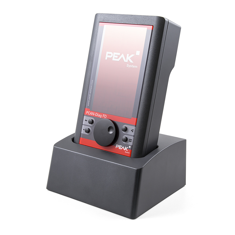
PCAN-Diag FD
Part No.: MPPK-PCAN-Diag-FD
MPPK-PCAN-Diag-FD+CS (+charging station)
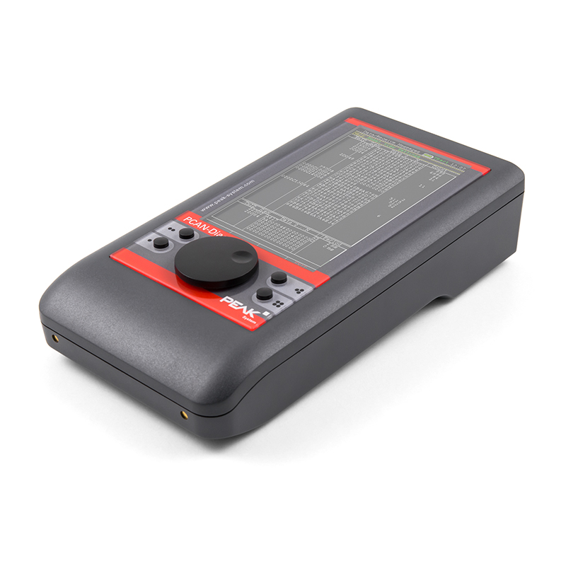
The PCAN-Diag FD is a handheld device for diagnosis of the communication on a CAN bus.
Product Description
Mobile Diagnostic Device for CAN and CAN FD Busses
The PCAN-Diag FD is a handheld device for diagnosis of the communication on a CAN bus. Possibilities for diagnosis are available on the protocol layer by handling CAN 2.0 and CAN FD messages as well as on the physical layer by using the oscilloscope function and further measuring functions for voltage and resistance.
The oscilloscope function is used for a qualitative assessment of the signal course on the CAN bus. Two independent measuring channels sample both lines CAN-High and CAN- Low with up to 100 MHz. Based on the signal course, the PCAN-Diag FD decodes CAN frames and shows their elements in the scope graphics.
On the protocol layer, the incoming CAN traffic is shown in a list, optionally with symbolic representation for better interpretability. For future analysis, a tracer is implemented that records the CAN traffic. On the outgoing direction, single CAN messages or even full sequences of CAN messages can be transmitted on the connected CAN bus, e.g. in order to request diagnostic data. Recorded CAN traces can also be played back. All functions on the protocol layer are available for CAN 2.0 as well as CAN FD.
The new CAN FD standard (CAN with Flexible Data rate) is primarily characterized by higher bandwidth for data transfer. The maximum of 64 data bytes per CAN FD frame (instead of 8 so far) can be transmitted with bit rates up to 12 Mbit/s. CAN FD is downward-compatible to the CAN 2.0 A/B standard, thus CAN FD nodes can be used in existing CAN networks. However, in this case the CAN FD extensions are not applicable.
The PCAN-Diag FD is operated in a simple manner with a push dial and four function keys. The device is supplied either externally or by the internal batteries that are automatically charged during external supply. With the optional charging station, the charging process can be accelerated.
Technical Specifications
-
High-speed CAN connection (ISO 11898-2)
- Complies with CAN specifications 2.0 A/B and FD
- CAN FD support for ISO and Non-ISO standards
- CAN FD bit rates for the data field (64 bytes max.) from 20 kbit/s up to 12 Mbit/s
- CAN bit rates from 20 kbit/s up to 1 Mbit/s
- Microchip CAN transceiver MCP2558FD
- CAN bus connection via D-Sub, 9-pin (in accordance with CiA® 303-1)
- Display with 800 x 480 pixel resolution
- Portrait or landscape presentation depending on the function and device orientation
- Presentation on an external display via a micro HDMI interface
- Power supply via the internal rechargeable batteries or the provided supply unit (low-voltage socket on unit)
- Charging of the batteries is carried out with external supply, even during operation
- Charging station with quick-charging function available as an option (IPEH-003068)
- Internal memory card for saving projects. Can also be used as a USB mass storage device when connected to a PC
- Device operation via a push dial and 4 buttons
- Operating temperature range from 0 to 50 °C (32 to 122 °F)
Overview of functions
- Analysis of CAN and CAN FD networks at the physical and the protocol level
- Selection of the bit rate from a preset list or from multiple user-defined values
- Automatic bit rate detection based on a fixed value list
- Switchable listen-only mode
- Switchable silent startup function (listen-only mode at wrong bit rate)
- Symbolic display of incoming CAN messages using Symbol files, taking into account enums (lists of values), multiplexers, and ID ranges
- Symbol files can be set up using the Windows software PCAN-Symbol Editor supplied with this product
- Recording of incoming CAN messages to the internal memory card, if required, with CAN ID filtering
- Playback of trace files
- Conversion of trace data to various output formats using the Windows software PEAK-Converter supplied with this product
- Transmitting individual CAN frames or CAN frame sequences
- Decimal, hexadecimal, or binary entering of CAN data. Data change of a single transmission message during runtime
- Measurement of CAN bus load, displayed by means of a time diagram, switchable display of error frames
- Bus load time diagrams can be saved as Bitmap screenshots
- Measurement of the termination of the High-speed CAN bus, even while the system is running
- Switchable CAN termination for the connected bus
- Voltage measurement at the CAN connector (D-Sub) for pin 6 and 9
- Management of device configuration, transmit lists, Symbol files, and all recorded data (screenshots, trace, and CSV files) in projects
- Optional auto-reset on Bus Off
Oscilloscope functions
- Oscilloscope with two independent measurement channels, each with a maximum sample rate of 100 MHz
- Display of the CAN-High and the CAN-Low signals as well as the difference of both signals
-
Trigger configuration to various properties of CAN messages
- Start and end of frames
- CAN errors
- CAN ID of individual frames
- Bit rate switch of CAN FD frames
- External measurement devices can be triggered using the banana jack, 4 mm
- Depiction of raw CAN and CAN FD frames
- Decoding of CAN and CAN FD frames from the recorded signal trace
- Display of various properties and of measuring data of the decoded CAN frame using the Report function
- Current view can be saved as a Bitmap screenshot
- Memory depth can be set to up to 1 megasample
- Recorded sample data can be saved as a CSV file
- Extensive zoom functions
- Time measurement with a resolution of up to 10 ns
Features of the software PCAN-Diag FD Editor for Windows, supplied with this product
- Convenient configuration of all available settings
- Compilation of transmit lists and sequences
- Configuration of multiple bit rates per project
- Device configuration, transmit lists, transmit sequences, and Symbol files can be saved in projects
- Projects can be transferred to the memory card of the PCAN-Diag FD using an USB connection
Product Includes...
- PCAN-Diag FD with or without charging station. Delivered in shockproof plastic box
- Configuration software PCAN-Diag FD Editor for Windows® 10, 8.1, 7 (32/64-bit)
- PCAN-Symbol Editor for Windows®
- Conversion software PEAK-Converter for Windows® 10, 8.1, 7 (32/64-bit)
- USB connector cable
- Power supply unit with changeable plugs for Euro, U.S., and UK
- HDMI/micro HDMI connection cable
- Manual in PDF format
- Printed quick start guide
Note: The charging station is supplied with the PCAN-Diag FD power supply unit.