DriveSim-100 Driving Signal & Protocol Simulation System
Part No.: MP-CAN-OBD-DriveSim-100-Basic
MP-CAN-OBD-DriveSim-100-AFS
MP-CAN-OBD-DriveSim-100-AFS+Cluster
MP-CAN-OBD-DriveSim-100-Pro
This system simulates driving signals and controls the instrument cluster and AFS over CAN, enabling communication analysis for testing and development.
Product Description
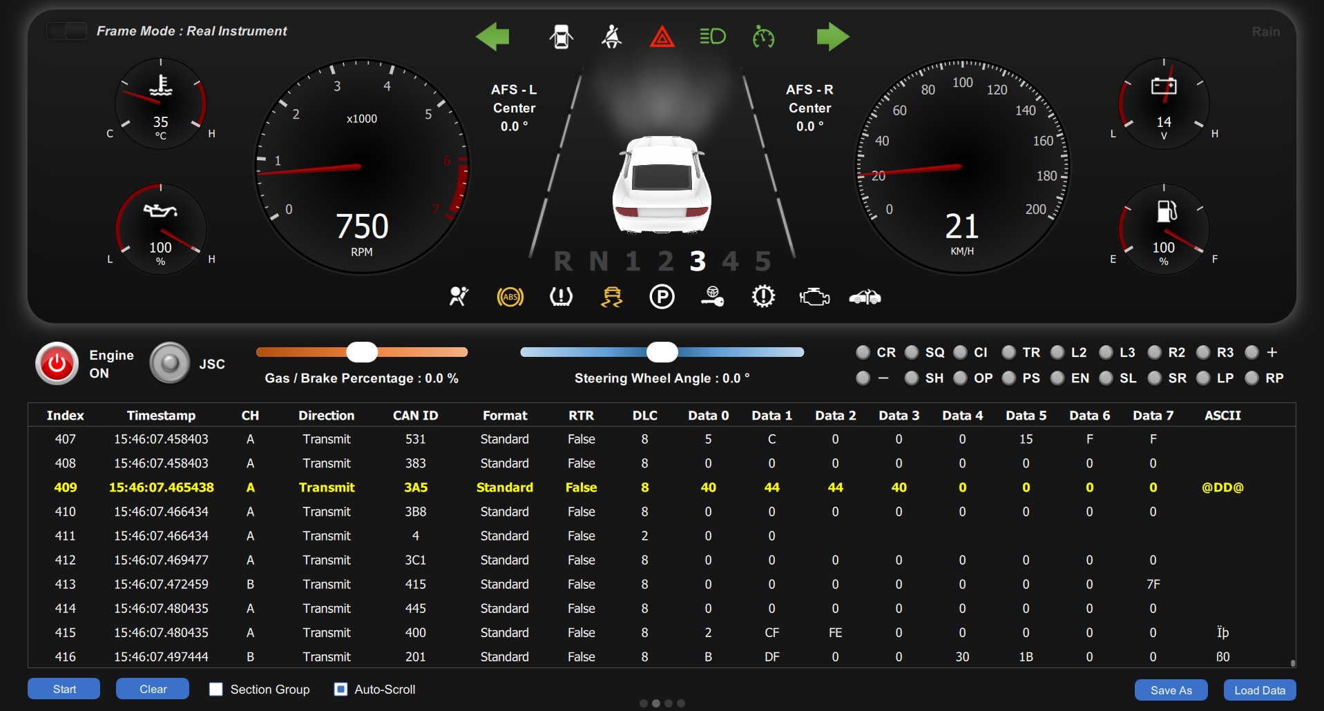
The system provides real-time control of the Instrument Cluster and Adaptive Front-Lighting System (AFS), allowing users to observe actual CAN Bus communication data during driving simulations. This enhances understanding of CAN communication structures and patterns, and serves as a platform for testing and further development in related fields.
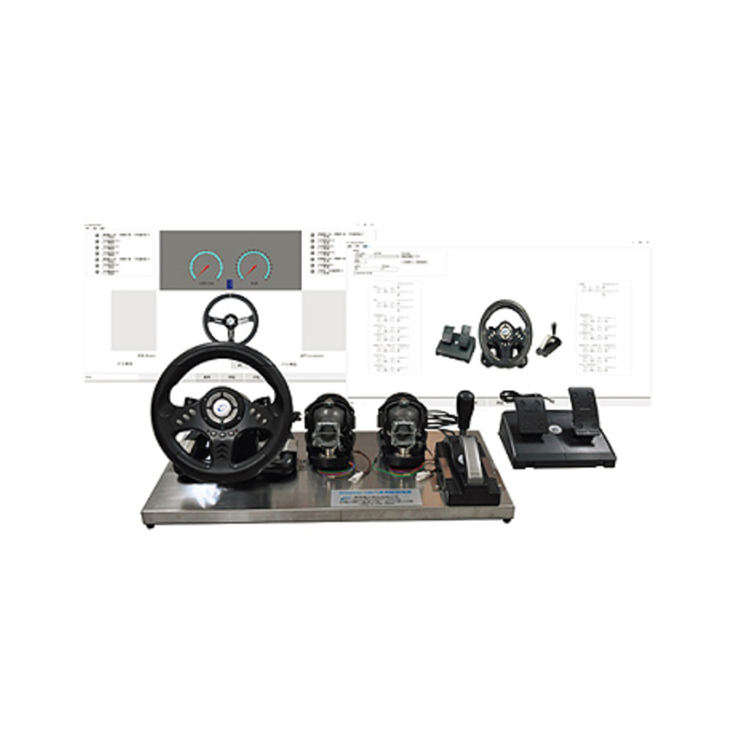
System / Hardware
Modules and Devices:
- Cluster Module (or Ford Mustang Cluster)
- Adaptive Front-Lighting System (AFS) Module
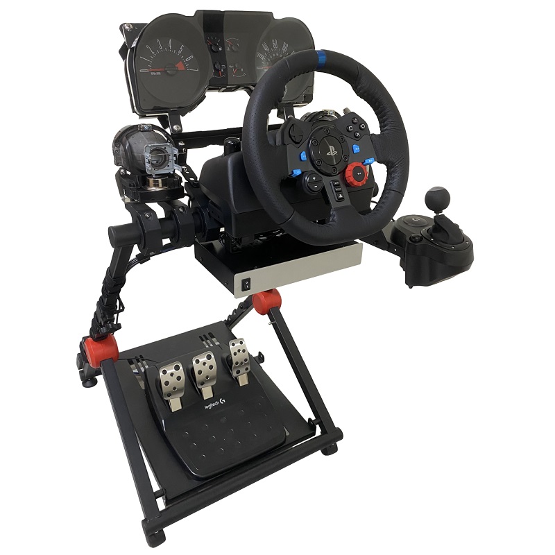
- Steering Wheel Controller (Logitech or PXN)
- CAN Bus Communication and Control Unit:
- Dual-channel CAN 2.0 A/B Interface (CiA 303-1 DB9)
- USB 2.0-to-CAN Interface
- Cluster Control Module
- AFS Control Module
- 12VDC / 5A Power Supply
.jpg)
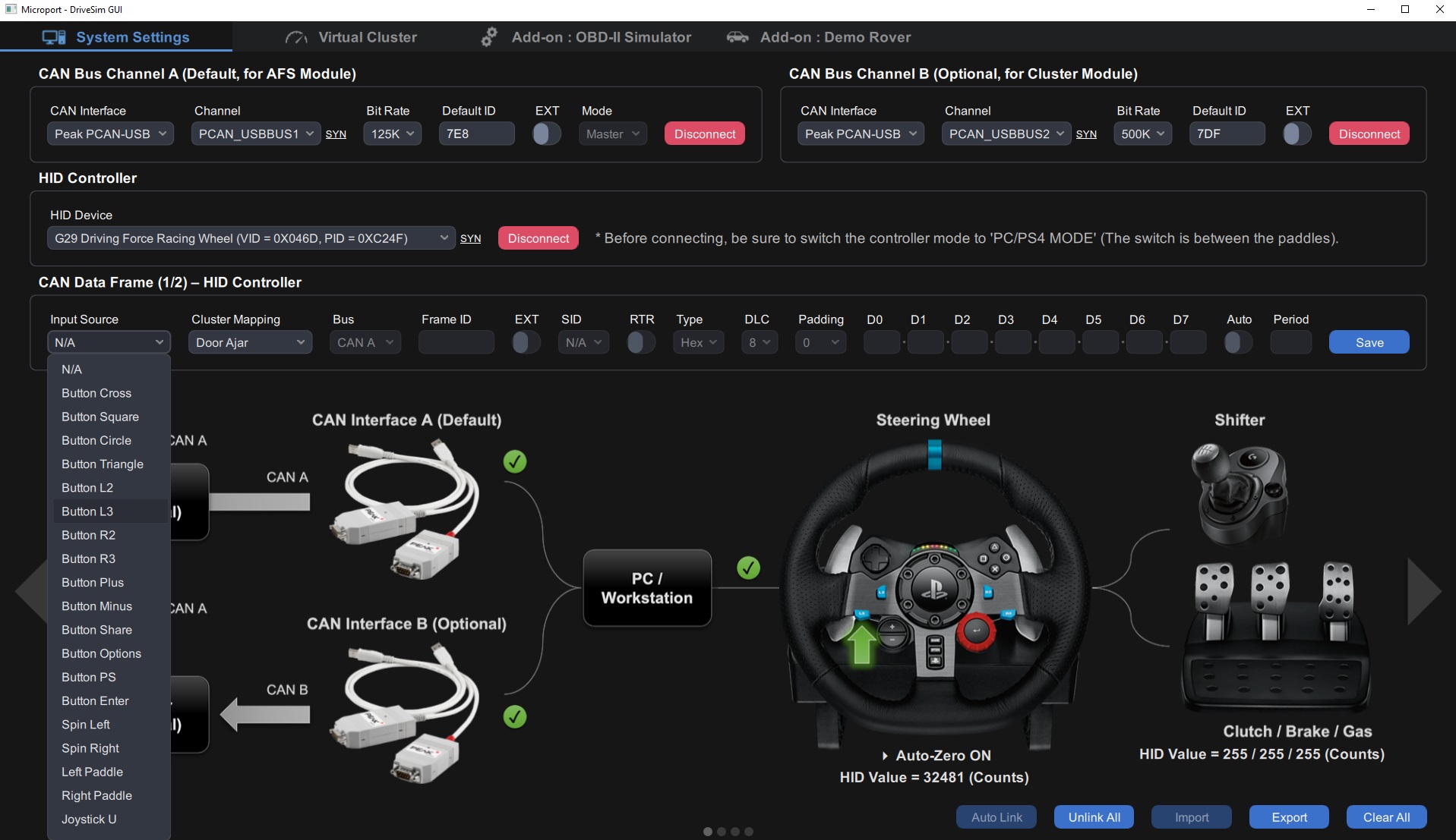
Software (Graphical User Interface)
Device Controller:
- CAN Control and Configuration, with customizable parameters for each channel.:
- Real/Virtual Interface
- Frame Format (Std 11-Bit/Ext 29-Bit)
- Bit Rate (125 ~ 1000 kbps)
Data Frame Editor:
- Editable items include 22 physical and 26 virtual input sources.
- High flexibility in editing detailed items of the CAN Data Frame.
- Controller Input Mapping functionality.
Virtual Cluster:
- Supports physical control of the controller or full virtual control.
- Displays real-time information with 6 types of gauges and 21 types of indicators.
- Allows free selection and drag to change values, with real-time interaction with the Cluster.
- AFS-related simulations:
- Supports Class V/C/E/W Mode (ECE324-R123).
- Real-time vehicle light status and inward/outward angle information.
- Allows switching between Dry/Wet weather conditions (for Class W).
- Supports road resistance RPM/Speed attenuation parameter settings.
Data Frame Monitor:
- Real-time display of CAN Data Frame, including ID, FF, DIR, RTR, DLC, DAT, DAT (ASCII), and other information.
- Section View, providing grouped data view of CAN ID.
- Data Logger, offering CSV export and import of CAN data.
Add-ons (Optional):
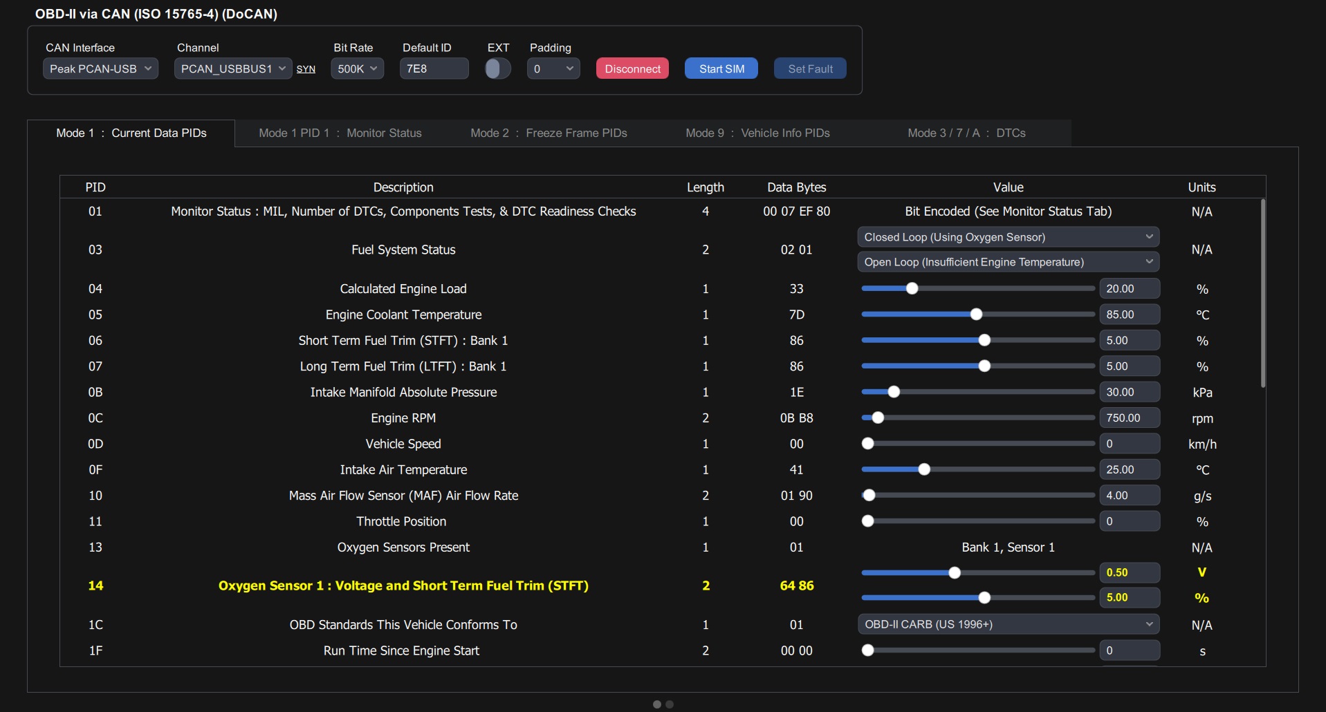
- Microport OBD-II Simulator Function Integration:
- Supports editing of OBD-II Mode 1/2/3/4/7/9/A information and related functionality operations.
- Real-time synchronization of PIDs and DTCs with simulated interactivity.
- Microport Automotive mmwWave Radar Module
- CanEduDev Demo Rover CAN Platform Control Function Integration