

1480A USB 2.0 Protocol Analyzer
Part No.: MPITIC-1480A-USB-2_0-Protocol-Analyzer
FPGA-based, fully upgradeable design. Real-time data capture and display.
此產品提供租賃服務,如有需求,請於此頁面底下填寫資料,我們將會儘快聯絡您。
產品介紹
1480A USB 2.0 Protocol Analyzer
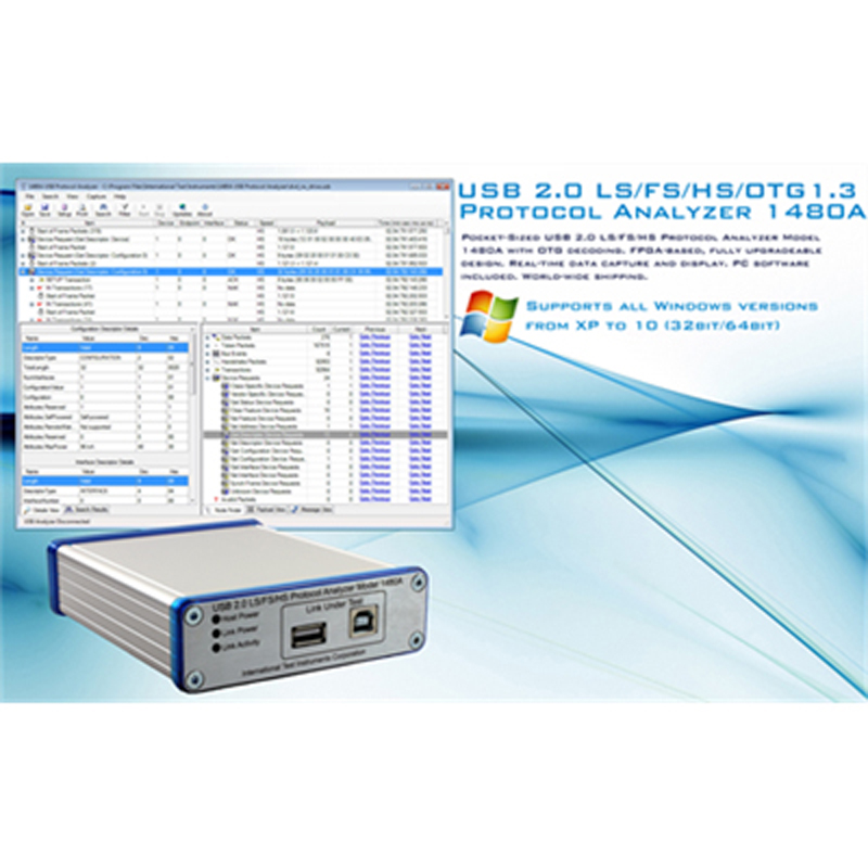
Pocket-Sized USB 2.0 LS/FS/HS Protocol Analyzer Model 1480A with OTG decoding. FPGA-based, fully upgradeable design. Real-time data capture and display. PC software included. World-wide shipping.
Unique Advanced Features
- The Hierarchical Protocol Tree View organizes the captured USB protocol data into a a format that exactly reflects the nesting of the actual USB protocol items on the bus. This greatly eases understanding of the USB protocol. Most other USB Protocol Analyzers use a primitive block-type display which makes it very hard to see the overall hierarchy of the complex data being communicated.
- Multiple time-correlated views of the data are simultaneously available, allowing you to easily see transaction, packet and bus-level details from the highest to lowest abstraction levels at a glance. Some other USB Protocol Analyzers require you to change the protocol view to view the data at a different abstraction level, resulting in loss of situational awareness of your location within the overall trace.
- The 1480A Decodes and displays all bus events down to the most detailed differential D-/D+ bus state changes with 16.67 ns resolution. Other USB Protocol Analyzers only show you the higher-level Protocol View without possibility to get to the lowest-level bus states.
- A very small physical format and a bus-powered design allows easy transportation and convenient use with laptops (only 4.90” x 4.10” x 1.4” / 8.8oz or 125 x 105 x 35 mm / 250g).
Description
The Model 1480A USB 2.0 Protocol Analyzer with OTG decoding is specifically designed for the road-warrior. It will easily slip into your coat pocket or laptop bag for those trips where bringing a large USB analyzer is not convenient. The physical format is very small, only slightly larger than a pen or a computer mouse. The enclosure is made out of very high-quality brushed aluminum.
The data captured is in real-time transferred to the Analysis PC where it is analyzed and displayed by the PC Software. The USB Analyzer has no limitation of the data size captured as data is streamed in real-time directly from the link under test into the PC application's tree view display. This allows you to capture many hundreds of MB of data (only limited to the size of RAM in your analysis PC).
The 1480A contains a 32MB FIFO buffer SDRAM that smooths out bursty traffic such that temporarily bursty traffic on the link under test will not cause the USB Analyzer-to-Analysis PC link to be saturated. The sustained maximum capture speed to the analysis PC largely depends on the speed of the capture PC. As a rule of thumb, as long as the throughput on the link under test is under 15 MB / s then the analysis PC will keep up with the captured data speed without the buffer FIFO filling up. Note that the 1480A USB Analyzer will never lose captured data (regardless if the link under test is saturated) since the captured data is always buffered in the SDRAM FIFO before being sent to the analysis PC.
The 1480A USB Protocol Analyzer is FPGA-based which makes it fully programmable with each new software upgrade. This allows us to fully remotely deploy logic and software upgrades, if needed. This means that you will never need to send your hardware to us for upgrade as more advanced software like class decoders are purchased.
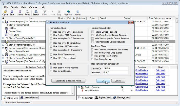
The PC Analysis Software displays data as it is received from the USB Analyzer hardware so you will not have to wait for lengthy data decoding before you can start analyzing the captured data. As USB Transactions and Packets are captured, they will be decoded and added to the tree view in the PC Analysis software. This makes it very easy to understand the sequence of events in the captured data. Detail views display the details for selected Transactions and Packets in the tree view as they are clicked on. The PC Analysis software also decodes payload data in hex format and displays it in the hex view pane.
The USB analysis software is free. It includes sample LS, FS and HS data files that can be viewed in the software, enabling you to get familiar with the Software before buying the USB Analyzer hardware.
What's in the box?
- 1480A USB 2.0 Protocol Analyzer.
- Two 3ft (1m) USB 2.0 cables.
- Installation CD containing drivers and software.
Technical Specifications
| 1480A LS/FS/HS USB Protocol Analyzer Technical Specifications. | ||
|---|---|---|
| Dimensions/ Weight | 4.90” x 4.10” x 1.4” / 8.8oz (125 x 105 x 35 mm / 250g) | |
|
Analysis PC Requirements |
32-bit (x86) and 64-bit (x64) Windows versions (XP SP2 or newer). Pentium 4 or faster CPU is recommended. |
|
|
Supported USB Standards |
USB 1.0, USB 1.1, USB 2.0, OTG 1.3. | |
|
Supported USB Speeds |
The 1480A automatically detects device connection in high speed
(480 Mbps), full speed (12 Mbps), and low speed (1.5 Mbps).
Note: HS Devices are initially connected as FS devices. Only after
successfully having completed the Device and Host Chirp Sequences do HS-capable devices enter HS mode. The 1480A fully supports automatic detection of both Device and Host Chirp. |
|
|
Maximum Recorded Data Length |
Unlimited. Only the available disk and memory of the Analysis PC limits how much data can be captured and analyzed. |
|
| Built in FIFO buffer |
32 MB. The FIFO buffer is used to smooth out the data stream captured from the Link Under Test. Note that the FIFO buffer will fill up if the Analysis PC is unable to read out data fast enough from the 1480A. In this case, the recording will automatically stop and the PC application will display the captured data up until the point where the FIFO filled up. |
|
| Analysis PC Interface | USB 2.0 Type "B" Connector | |
| Link Under Test Interface | USB 2.0 Type "A" and "B" Connectors. | |
| LED Indicators |
|
|
| Captured bus events and packets |
All bus activity down to the smallest detail is captured and stored into the .usb file when recording. The 1480A Software displays all the captured information from the lowest link level up to the highest protocol level. In addition the VBus voltage is continuously monitored and stored in the capture file. |
|
| Displayed Bus Events |
LS Device Connection, FS Device Connection, HS Device Connection, Device Reset, Device Chirp, Host Chirp, Device Disconnection, HS Idle, Keep-Alives, OTG Session Request Protocol, OTG Host Negotiation Protocol and OTG VBus events. |
|
| Displayed Packets |
SETUP, IN, OUT, SOF, DATA0, DATA1, DATA2, MDATA, ACK, NAK, NYET, STALL, PING, SPLIT, PRE. |
|
| Displayed Transactions |
SETUP Transaction, IN Transaction, OUT Transaction, PING Transactions, SPLIT Transactions. |
|
| Decoded Device Requests |
CLEAR_FEATURE, SET_FEATURE, SET_ADDRESS,
GET_DESCRIPTOR, SET_DESCRIPTOR, GET_STATUS, GET_CONFIGURATION, SET_CONFIGURATION, GET_INTERFACE, SET_INTERFACE, SYNCH_FRAME.
Note: All Device Requests are captured and displayed but only
standard Device Requests are decoded. I.e., non-standard Device Requests (not listed above) will be displayed in hexadecimal form. |
|
| Decoded Descriptors |
Device Descriptor, Configuration Descriptor, Interface Descriptor,
Endpoint Descriptor, String Descriptor, Device_Qualifier Descriptor, Other_Speed_Configuration Descriptor and OTG Descriptor.
Note: Class-specific descriptors are currently not decoded but instead
displayed in hexadecimal form. Class Decoders, sold separately when available, will fully decode related class-specific descriptors. |
|
| Packet Integrity Checked |
|
|