產品介紹
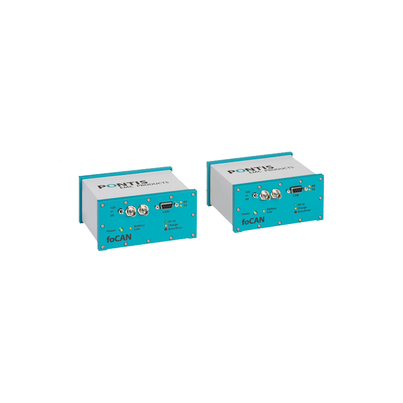
In complex testing environments, it is often needed that electrical signals have to be transmitted into the chamber, or out of the chamber to the test equipment.
For that purpose, we offer a variety of different interfaces that convert electrical signals into optical signals and back. Such the signal can be transmitted via fibre optics and is immune against electrical fields.
A sophisticated shielding and filtering concept ensures that the interfaces are highly immune against radiation, and do not deliver out any significant emission. In most cases both units are shielded.
- High speed ISO11989-2
- 50–1000 KBaud (down to 10 on request)
- Unbuffered
- Distance depends on speed
- EMC compliant to CISPR 25, Class 5. Battery version -10 dB
Features
- RF-Immunity: Antenna radiated 200 V/m, 200 MHz –18 GHz, ISO11452-2, CW, AM, PM / Stripline 600 V/m, 10 – 1 GHz, ISO11452-5, CW, AM, PM
- Emission: EMC compliant to CISPR25 Class 5, 150 k-4 GHz, Battery version: -10 dB
- Battery (approx. 8 hours operation) or mains powered
- Compact metal housing
- No galvanic connection between test equipment and measurement instrument
- Max. distance: 10 m at 1000 kbit (longer length at lower speed possible)
Specifications
| Allowed CAN-DC-levels | Up to +30V, CAN H/CAN L to GND |
|---|---|
| Recessive bus level | 2,5V to GND |
| Physical CAN specification | ISO 11898-2, 20-1000 kBit/s |
| Selectable CAN bus termination | 120, 60 Ohm or none |
| Data transmission | transparent, unbuffered |
| Data signaling rate | 50 – 1000 KBaud (down to 10 in special conditions, on request) |
| Electrical connector | DSUB, 9-pin, male, 2 Can L, 3 GND, 7 Can H |
| Fibre optic connection | FST |
| Fibre optic cables |
multimode duplex fibre, 50/125 μm maximum fibre length depends at operation mode an CAN bus speed 10 m at 1000 kbit, longer length at lower speed possible |
| Wavelength | 850 nm |
| Charging input | 12V DC, 1A, mains power supply or recharchable battery |
| Compatibility | can operate with 24 V vehicles |
| Operating temperature | 0 °C / +40 °C |
| Operating humidity | 20 to 85 % RH |
| Weight per converter | 0.8 kg |
| Housing | passivated aluminium, grey-petrol |
| Dimensions per converter | 103 x 127 x 67 mm (LxWxH) |
Accessories
Standard
- One set consists of two converter units
- All interfaces are shipped with the appropriate power supply or battery and charger.
Optional
- Fibre optic cables: variable lengths ST/FSMA-connector or ST/ST-connector
- FO-Patches (Feed Through wall Patches)