Hybrid and All Electric Vehicles Technology Trainer
Part No.: MPLCNL-Hybrid-and-All-Electric-Vehicles-Technology-Trainer
Hybrid motor vehicles and electric cars are not just a future consideration, but in fact the auto industry has already made them available on the market.
產品介紹
Hybrid and All Electric Vehicles Technology Trainer
When we think about the future of our planet the development and production of vehicles equipped with hybrid drives is a logical and necessary step. Lower emissions and less fuel consumption are benchmarks for future generations of modern automobiles. Such measures ensure that the fundamentals necessary for life are sustained while quality of life improves. Hybrid motor vehicles and electric cars are not just a future consideration, but in fact the auto industry has already made them available on the market. The only rational diagnostic strategy available for these vehicles presupposes the necessary system understanding.
List of Articles
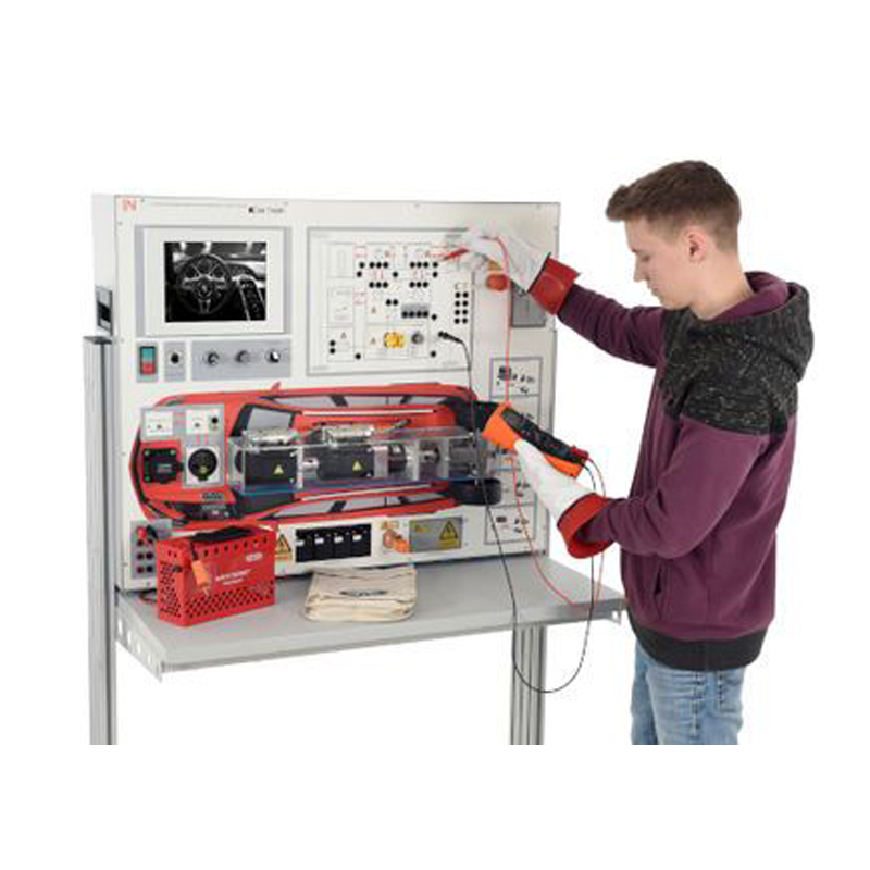
CarTrain "Hybrid and Electric Vehicles"
Trainees work directly on a real high-voltage system, which has nevertheless been adapted with special safety features so that it can be used without any prior qualifications. Thus this training system provides a safe work environment and allows students and trainees to fully focus on the task at hand. All the content is based on the world wide existing curriculums like DGUV 200-005 , IMI EV Qualifications or ASE L3. Trainees can become familiar with all the key theoretical background by means of an interactive e-learning course. Each of the theoretical sections is accompanied by practical exercises and tests of knowledge, which also help to advance vital diagnostic skills. These skills are further boosted by the built-in diagnostic system and the scrupulously selected fault scenarios. This is the only training system which gives students the opportunity to develop various diagnostic strategies involving measurements on an actual HV system with real HV voltages under the most stringent safety conditions.
Special features of the training system:
-
High-speed CAN as communication bus integrated into the HV system control.
- Communication between HV charging system, HV battery and inverter.
- Voltage values read out as CAN messages.
-
12V battery integrated into the disconnection and isolation process
- Incl. fast-action battery terminal for tool-free disconnection of the negative pole
- Real fault codes for all diagnostics cases
- Extended interlock (service maintenance plug, HV measurement point)
- Real service maintenance plug
- Complete preload sequence for booting up HV system
- Active discharge - function for rapid shut-down of the HV system
-
Reworked user interface with new "Virtual Cockpit"
- With power meter
- READY display
- Extended tester functionality incl. tester-guided disconnection and isolation
-
Display of the actual values in the tester:
- Voltage of the link circuit, traction battery
- Illustration of the switch-on process (preload phase)
- Status polling of HV relay
- Status polling of interlock
- Voltage of PP contact
- Status polling of charging process
- Upgrade of fault simulation (e.g. adjusted response to insulation faults)
- New Labsoft course with lots of new content
- New front panel design
Includes:
- "CarTrain Hybrid and all-electric vehicles" training course
- USB-ethernet network adapter
- 5 Overlay masks for various drive systems
- Operating instructions
-
Interactive training course on data media
- Illustration of the content of DGUV 200-005
Integrated brand-independent drive concepts:
- Serial hybrid drive with plug-in capability
- Parallel hybrid drive with plug-in capability
- Serial-parallel hybrid with plug-in capability
- All-electric vehicles
- Fuel-cell vehicles
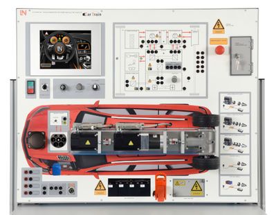
Set-up of the training system
- On the front there are two motor-generator units and two transmission systems which transfer drive power to the two wheels on the rear axle.
- Different overlay masks are used to depict the various types of drive and vehicle. In addition to the graphic representation of the relevant block circuit diagrams, direct measurements covering individual electrical components and the flows of energy between them can be made with the aid of the diagrams themselves.
- A capacitive colour touch panel, 10.4 inch, offers a view of the instrument cluster for the vehicle in question.
- The touch panel can also be used to invoke the built-in engine tester.
- Also on the colour touch panel, force and energy dynamics can be shown as animations which are based on the original vehicles themselves.
- A potentiometer can be used to reset the speed of the vehicle as required.
- Another potentiometer enables the energy available from the HV battery to be adjusted between 0% and 100%.
- The driving profile is changed between uphill, level and downhill road conditions using a switch.
- The vehicle is started using a 3-stage ignition switch.
- The system is equipped with batteries connected in series, in order to clarify the principle behind series connection of the traction battery.
- A service maintenance plug (incl. interlock contact) is located on the front panel in order to de-energise the high-voltage system.
- Measurement sockets to enable verification that the system is de-energised (voltage free) are located behind a lockable cover (incl. interlock contact).
- There are also externally accessible 4-mm measuring sockets directly connected to the resolver. Sine and cosine voltages from the resolver can thus be measured directly.
- 4-mm measuring sockets are also accessible for equipotential bonding.
- Other 4-mm safety measuring sockets are provided in order to measure screening of the wiring.
- There are also externally accessible 4-mm measuring sockets directly connected to the inverter.
- Measuring sockets for motor/generator 1 are provided in the form of 4-mm measuring sockets.
- Measuring sockets for motor/generator 2 are provided in the form of 4-mm measuring sockets.
- A fully functional type 2 charge terminal for connection to a charging station conforming to IEC 61851-1 is also installed.
- Measuring sockets for demonstrating safety communication between the charging station and the vehicle via an interlock contact are also available in the form of 4-mm safety measuring sockets.
- To aid faster understanding, the right-hand side of the front panel features a graphic representation of each drive configuration implemented in the system.
- An emergency stop switch is also located on the front panel.
- The system as a whole can be connected to a PC with the help of a USB cable. A built-in measuring instrument allows all measurements on the system to be recorded and sent to the computer via the USB link.
- A lockable fault simulation switch box makes it possible to emulate an extensive variety of fault scenarios.
- Measurements of insulation resistance can also be made using an instrument which is supplied with the training system.
- HV system implemented as an IT network.
- Two-voltage on-board power supply system
- Charge enabling switch
- Preparation for inductive charging
Integrated WiFi measurement interface:
- Connection via USB port or via wireless WLAN
-
4-channel oscilloscope with trigger, cursor and freeze function
- Four floating voltage inputs for voltages up to 500 V AC/DC
- Voltmeter
- Ammeter
-
Student specific saving of measurement results inside the E-learning course
- Saving per copy & paste - function
- Function generator output
- Resolver reference signal
- Variable voltages and waveforms via function generator
- Variable signals via frequency generator
- Variable voltages via three-phase supply
- Variable voltage and phase-shift via extended three-phase supply
Performing the following measurements:
- Charging processes of the traction battery
- Discharging processes of the traction battery
- Voltage measurements on the traction battery
- Verifying voltage isolation
- DC link circuit voltage
- Insulation resistance measurement
- 3-phase measurement on motor/generator 1 (power and recuperation)
- 3-phase measurements on motor/generator 2 (power and recuperation)
- Sine and cosine voltages from resolver
- Measurement of equipotential bonding
- Shielding measurement
- CP contact in charging system
- Analysis voltage in charging system
- Charge voltage in plug-in system
- The maximum voltage amplitude is approx. 425 V AC and approx. 320V DC
- Charge system based on DIN IEC 61581-1
Practical training contents:
-
Servicing work
- Correct selection and testing of suitable instruments and testing equipment
- How to use service information
- Carrying out service work on HV systems
- Checking charging device
- Charging of high-voltage battery
-
Repair work
- Measurement at potential equalisation conductors
-
Disconnection and isolation of a HV system
- Manual disconnection and isolation
- Tester-guided disconnection and isolation
- Securing against reactivation
- Verification of isolated status (absence of voltage)
- Putting a HV system into initial operation
- Measurement of insulation resistance
- Measurement of the shielding
- Measuring the temperature (traction battery, E-machine)
-
Diagnostics work
-
Fault localization on a HV system
- Fault finding on electric motor
- Fault finding on the inverter
- Fault finding on the connection lines
- Measurement of the equipotential bonding
- How to use the diagnostic device
- Read-out and deletion of fault memory
- Measurement on the CAN bus
-
Fault localization on a HV system
Course contents:
- An interactive course is supplied, which contains the following topics:
- Smart grids
- Criteria for putting the test equipment into operation
- Selection and checking of the test equipment
- Drive concepts
- Drive configurations
- Drive variants
- Operating modes
- Health and safety while working
- Electrical hazards
- Passage of electricity through the human body
- Hazards due to AC
- Safety regulations
- HV battery
- Batteries made of nickel-metal hydrides
- Lithium-ion batteries
- Cooling of battery systems
- Meaning of "high voltage (HV)"
- Electricity "fuelling" stations
- Working with high-voltage vehicles
- On-board power networks in high-voltage vehicles
- Intrinsically safe HV vehicles
- Safety concepts for high-voltage vehicles
- Vehicle-internal safety concepts
- Switch-on current and current limiting
- Serial hybrid drive with plug-in capability
- Parallel hybrid drive with plug-in capability
- Serial-parallel hybrid with plug-in capability
- Axle-split parallel hybrid
- Power-split hybrid drive
- Other drive configurations
- Hybrid driving
- Pure electric driving
- Generator operation
- Boosting
- Regenerative braking
- Electric drive systems for hybrid vehicles
- Electric vehicles
- Hydrogen-fuelled electric vehicles
- Design of electrical machines
- Asynchronous machines
- Synchronous machines
- Control units for hybrid drives
- Rectifiers
- Inverters
- Regenerative braking and energy recovery
- Fault finding in traction motor circuits
- Fault finding in inverter circuits
- Fault finding in screening circuits
- Fault finding in equipotential bonding circuits
- Fault finding in battery circuits
- Operating principle for resolvers
- Operating principle for interlock contacts
- High speed - CAN bus
- Measurement of the CP signal of type2 charge connection during active charging process
-
How to handle damaged HV vehicles
- Safer handling by rescue services
- Disconnection and isolation options for rescue services
- Special hazards
- Rescue scheme for rescue services
Dimensions and power supply
- Voltage supply AC 230 V, 50-60 Hz/3 A
- Dimensions: 1000 x 800 x 220 mm (WxHxD)
- Weight: 72 kg approx.
Additionally Required
Safety Zone for Hybrid and Electric Vehicles (Chain Version)
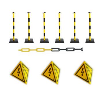
This set gives you a handy alternative for setting up a complete safety zone for working with high-voltage hybrid and electric vehicles or their high-voltage batteries. Six securely free-standing poles with cordon chains allow you to set up a safety zone which meets the safety demands. Such a safety zone needs to be set up to secure high-voltage vehicles or their HV components and to protect trainees in laboratories or repair shops. For any work on a high-voltage battery it is essential for the area to be cordoned off. Setting up a safety zone is therefore an essential aspect of any training.
The cordon poles require no maintenance and the tensile strength of the chains has been optimised.
This guarantees the highest level of safety and durability. The three magnetic roof pylons can be simply attached to the roof of a vehicle without any tools. Everything in the set is a certified and tested safety product.